Where do five ECE R37 H11 LEDr samples differ in construction and measured performance? This review follows EB, OSRAM, Philips, E4E and Luxfighter from their packaging and mounting components to their emitting structures and projected beams. The photographs show how each lamp is built and where its light appears; nine-point illuminance, surface-temperature and fan-noise measurements reveal the differences beyond appearance.
Test conditions. One lamp from each product was tested at 13.2 V in a room at 26°C. After 30 minutes of operation, illuminance was measured at nine reference points on a screen 3.5 m away, and surface temperature was recorded at the LED emitting area. Fan noise was measured 3.5 cm from the fan. The results describe these five tested samples; the 3.5 m setup is a comparative test, not a type-approval test.
Individual test records: EB H11 LEDr review · OSRAM H11 LEDr review · Philips H11 LEDr review · E4E H11 LEDr review · Luxfighter H11 LEDr review
Pairwise comparisons: EB vs OSRAM · EB vs Philips · EB vs E4E · EB vs Luxfighter
Core Results
| Five-Product Measurement Overview | |||||||
|---|---|---|---|---|---|---|---|
| Product | Package volume (L) | Empty package (g) | Opposing-surface distance (mm) | EMAX (lux) | B50L (lux) | Surface temperature (°C) | Fan noise (dBA) |
| EB | 0.779 | 51 | 1.154 | 1,741 | 34.4 | 67.3 | 54.6 |
| OSRAM | 1.248 | 90 | 2.446 | 1,670 | 32.0 | 74.3 | 48.9 |
| Philips | Pending update | Pending update | 2.245 | 1,735 | 32.9 | 83.8 | 56.7 |
| E4E | 0.392 | 28 | 2.511 | 1,593 | 29.4 | 111 | 61.9 |
| Luxfighter | 0.972 | 44 | 2.468 | 1,523 | 35.5 | 110 | 51.3 |
Philips packaging was damaged in transit. Its packaging photographs and measurements are pending an update when replacement materials are received. Package volumes are calculated from the external dimensions; surface temperatures and fan-noise levels use the conditions stated above.
Packaging and Retail Presentation
Packaging affects both the space occupied by stock and how the product is presented. Contents, outer dimensions and empty-package weight are recorded separately so that a smaller box is not confused with a lighter one.
1. Package and Included Contents
Packaging was damaged in transit. Photographs and measurements will be added when replacement packaging is received.
Philips — pending update
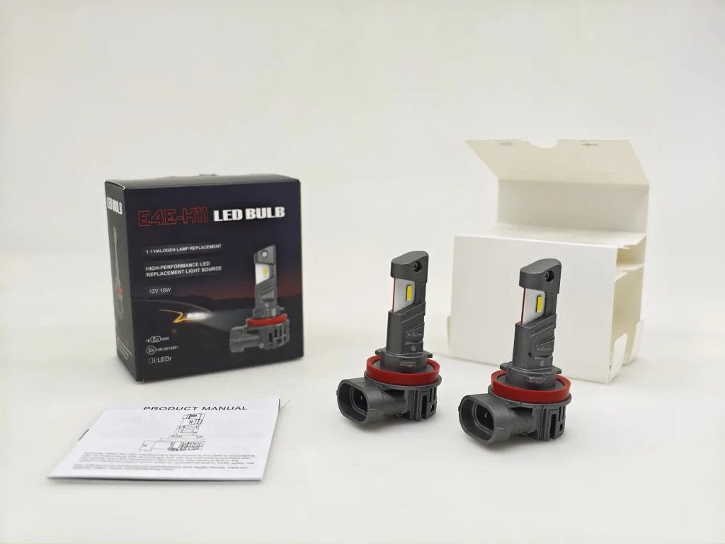
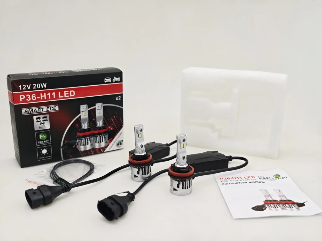
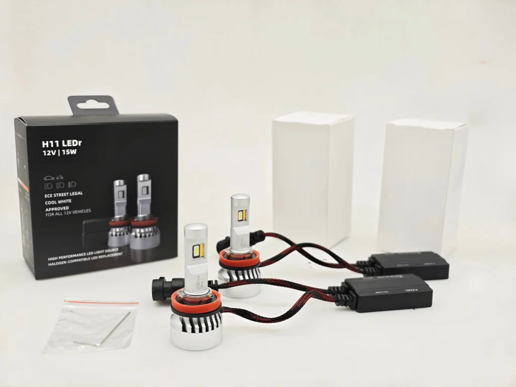
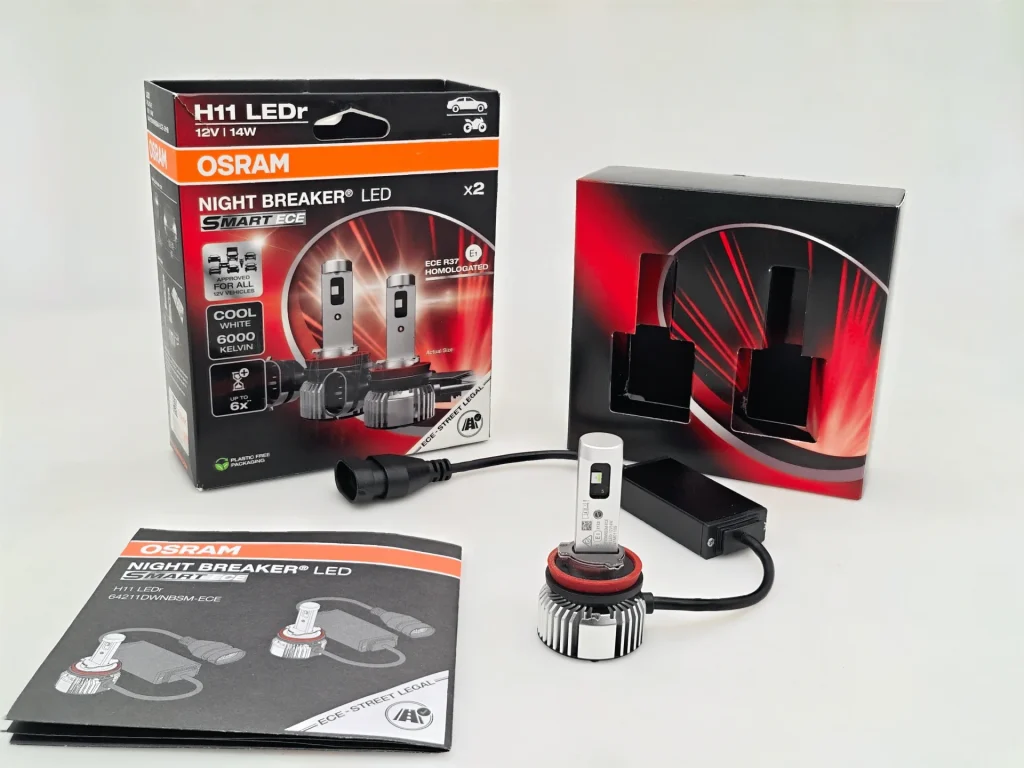
EB packs its lamps and separate drivers with two plain inner boxes and an accessory bag. OSRAM uses a formed insert and printed instructions. E4E packs one-piece lamps with a white inner box and manual, while Luxfighter uses foam support and includes a cable tie and instructions. EB and OSRAM have hanging features; the tested E4E and Luxfighter packs do not.
| Package Presentation: Key Differences | |
|---|---|
| Comparison focus | Recorded difference |
| Peg-hook display | EB and OSRAM include a hanging feature; E4E and Luxfighter do not. |
| Internal organisation | EB uses two plain inner boxes and an accessory bag; OSRAM uses a formed insert; Luxfighter uses foam support. E4E packs one-piece lamps in a white inner box. |
| Printed instructions | Present in the OSRAM, E4E and Luxfighter records. |
| Philips packaging | Photographs and measurements are pending an update following transit damage. |
EB and OSRAM are ready for direct peg-hook display. OSRAM gives the contents a fitted presentation, while EB separates the hardware into plain inner boxes. E4E and Luxfighter use box-based presentation without a hanging feature.
2. External Package Dimensions
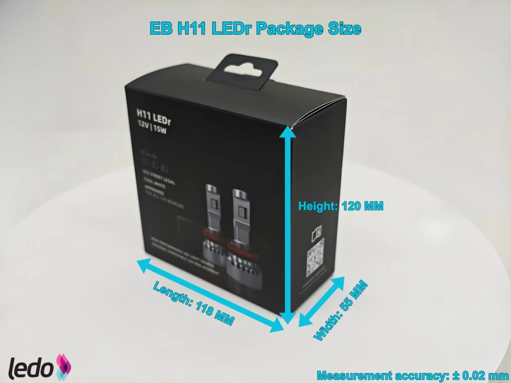
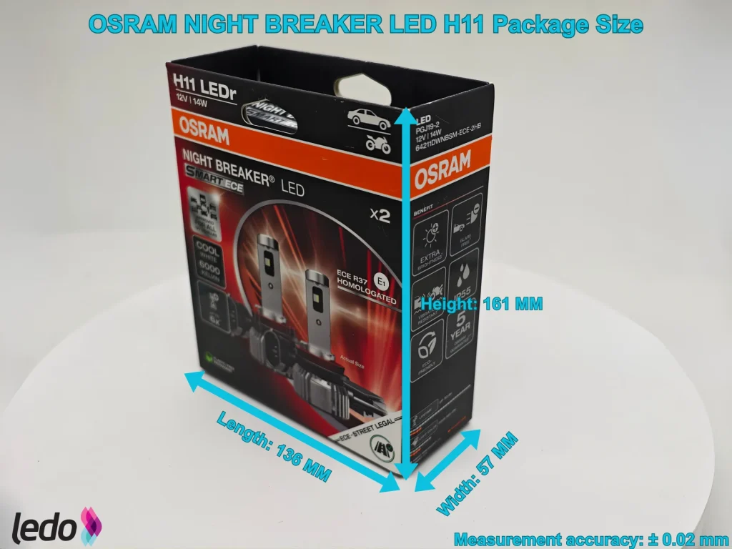
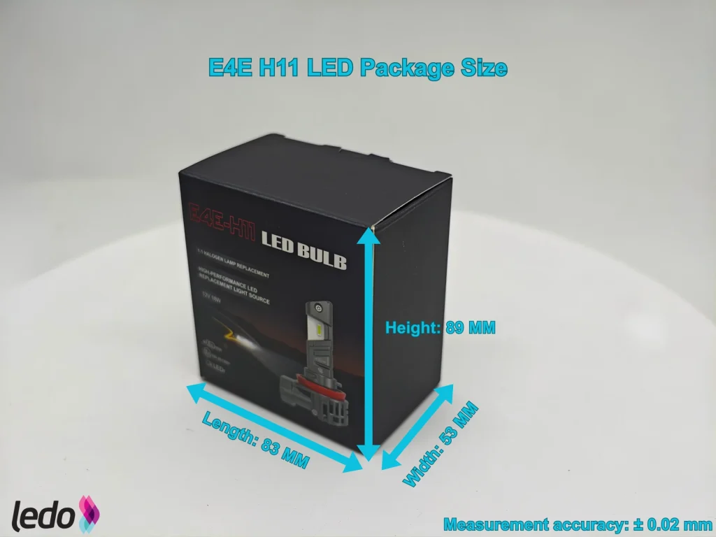
Length, width and height determine nominal box volume. These measurements give a common basis for comparing storage space before master-carton layout is considered.
Packaging was damaged in transit. Photographs and measurements will be added when replacement packaging is received.
Philips — pending update
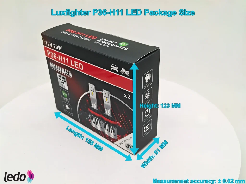
Packaging was damaged in transit. Photographs and measurements will be added when replacement packaging is received.
E4E is the smallest measured box in all three dimensions. EB occupies less total volume than Luxfighter despite being 4 mm wider, while OSRAM has the largest recorded volume.
| External Package Dimensions | ||
|---|---|---|
| Product | Dimensions (mm) | Nominal external volume (L) |
| EB | 118 × 55 × 120 | 0.779 |
| OSRAM | 136 × 57 × 161 | 1.248 |
| Philips | Pending update | Pending update |
| E4E | 83 × 53 × 89 | 0.392 |
| Luxfighter | 155 × 51 × 123 | 0.972 |
E4E uses the least packaging space. EB is next, using 37.60% less volume than OSRAM and 19.90% less than Luxfighter while accommodating separate drivers and supporting peg-hook display.
3. Empty-Package Weight
Weighing the empty package isolates the weight added by the packaging itself.
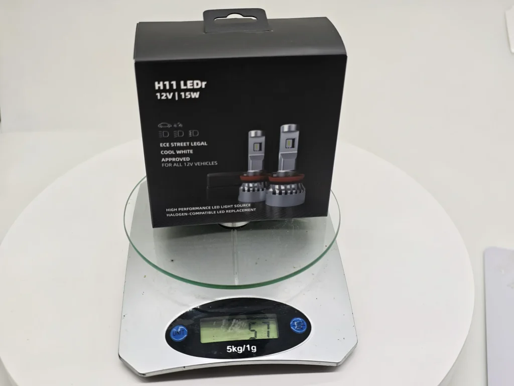
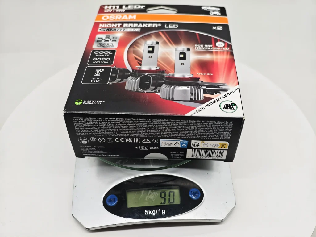
Packaging was damaged in transit. Photographs and measurements will be added when replacement packaging is received.
Philips — pending update
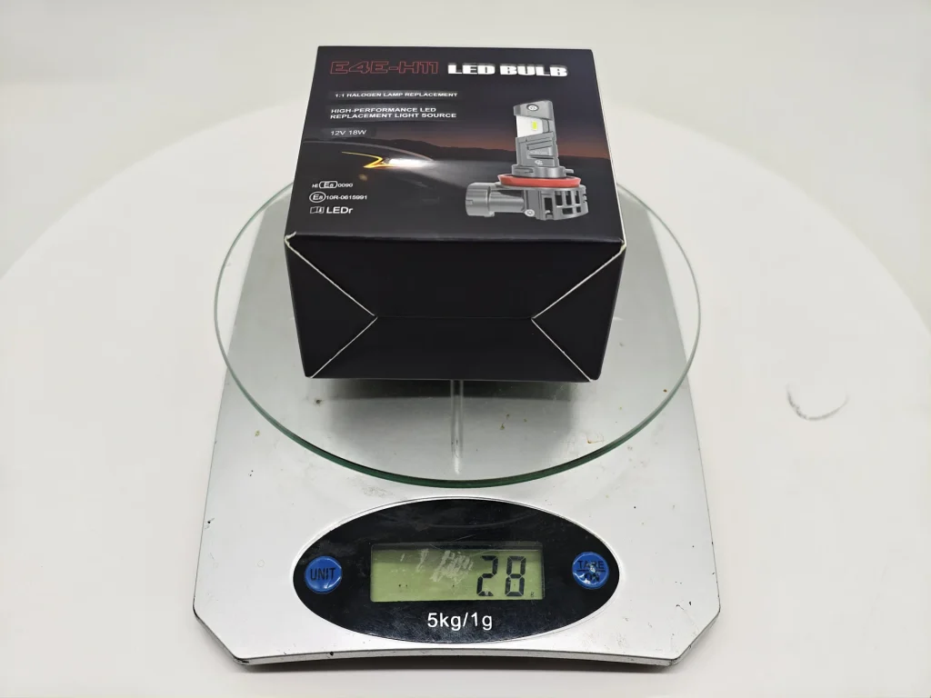
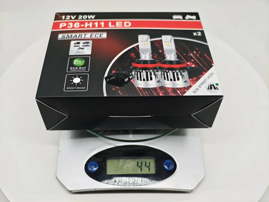
Packaging was damaged in transit. Photographs and measurements will be added when replacement packaging is received.
The empty packages range from 28 g for E4E to 90 g for OSRAM. Luxfighter is lighter than EB even though its box volume is larger.
| Empty-Package Weight | |
|---|---|
| Product | Recorded weight (g) |
| EB | 51 |
| OSRAM | 90 |
| Philips | Pending update |
| E4E | 28 |
| Luxfighter | 44 |
E4E combines the smallest volume with the lowest empty-package weight. Luxfighter saves 7 g per box against EB; EB saves 39 g against OSRAM. EB’s packaging strength is its combination of compact volume, moderate weight and a hanging feature.
Mounting and Lamp Construction
1. Lamp and Driver Layout
The cooling body, cable and driver occupy the space behind the mounting base. Their arrangement determines which components must be positioned and connected during installation.
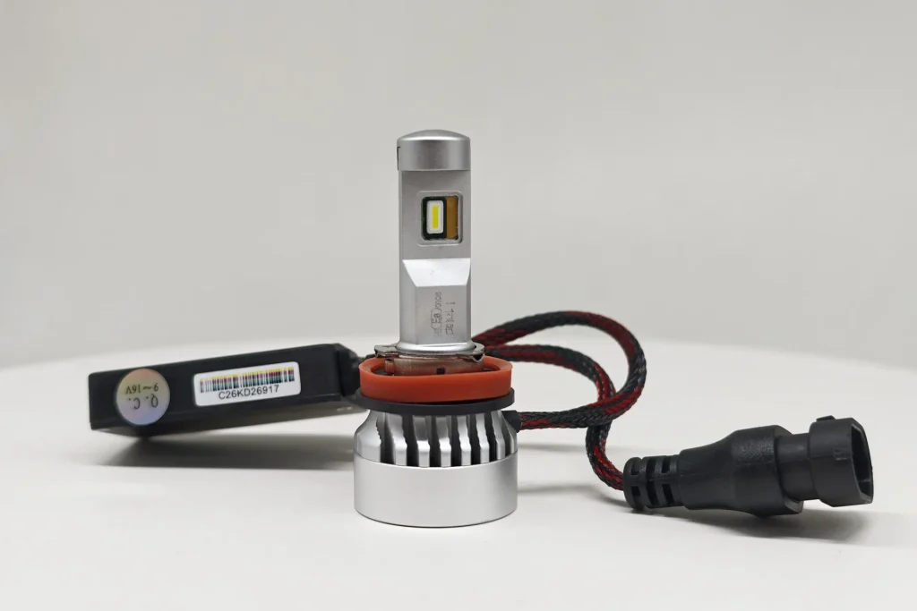
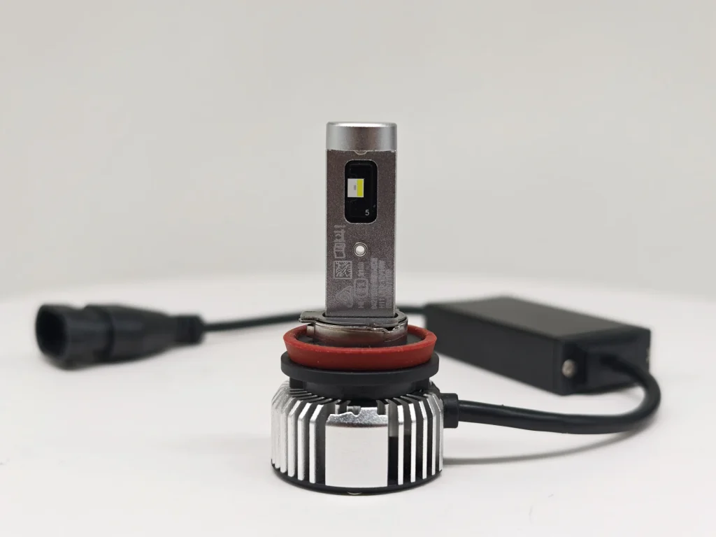
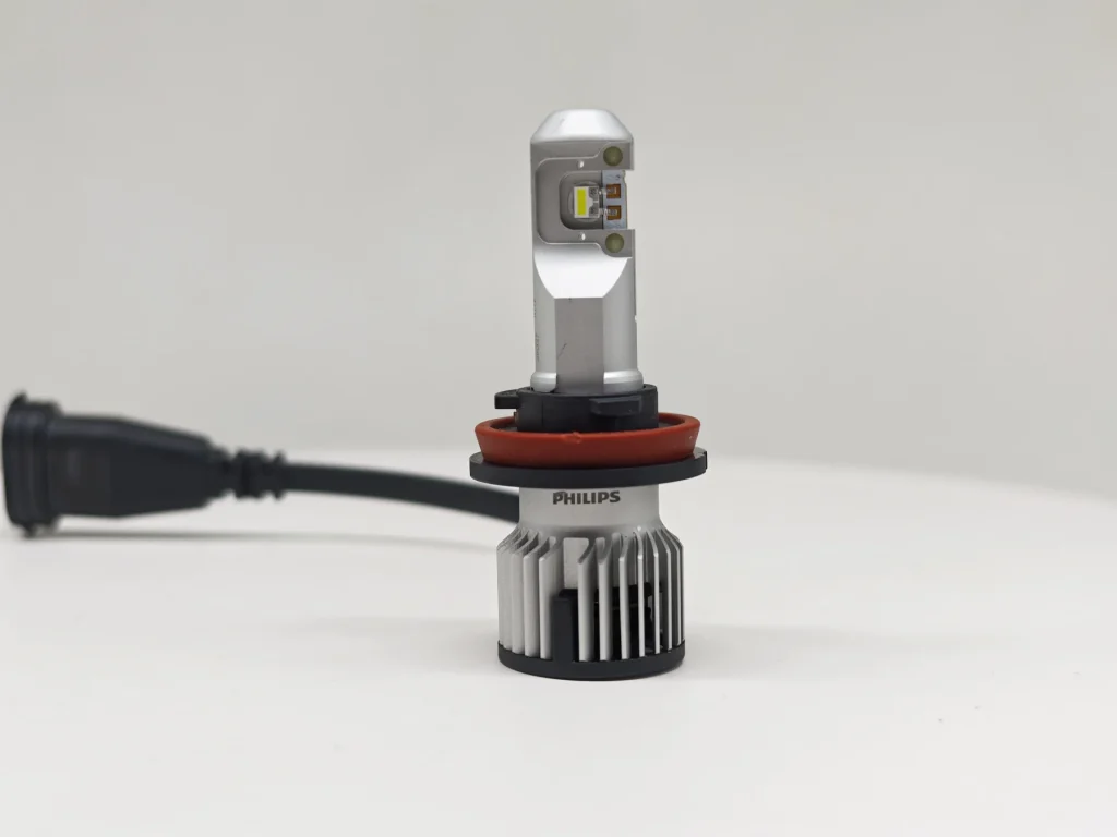
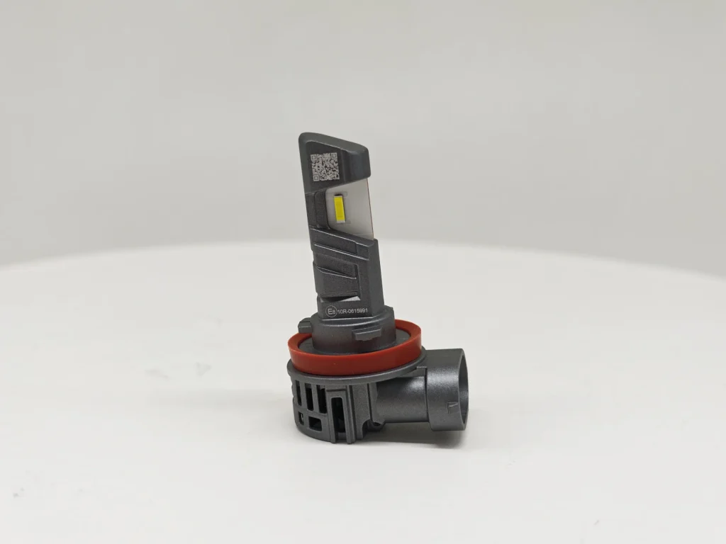
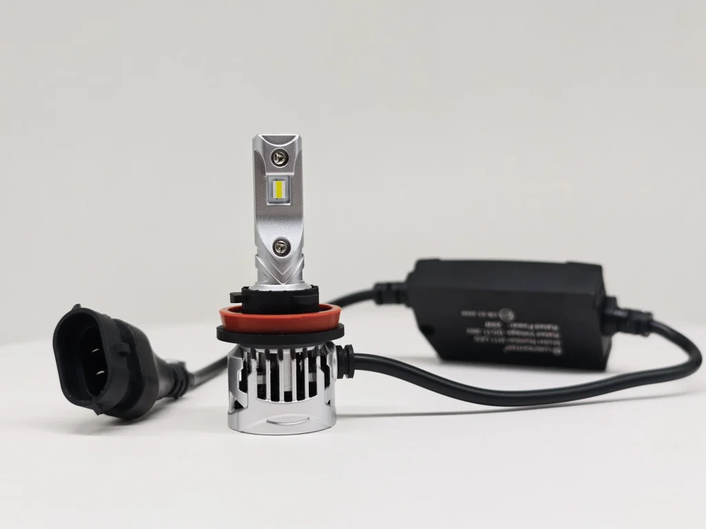
EB separates a narrow driver from its cylindrical cooling body and covers the leads with a braided sheath. OSRAM uses radial fins, smooth leads and a broader driver. Philips also has radial fins and a smooth cable, with no separate driver visible in this view. E4E places the connector on its rear fan housing; Luxfighter connects an open, slotted cooling body to a separate driver.
| Lamp and Driver Layout: Key Differences | |
|---|---|
| Comparison focus | Recorded difference |
| Separate or integrated layout | EB, OSRAM and Luxfighter have separate drivers. E4E integrates its connection into the rear housing. No separate driver is visible in the Philips view. |
| Driver profile and cable covering | EB combines a narrow driver with braided leads. OSRAM has a broader rectangular driver; Luxfighter has a moulded driver. Both use smooth leads. |
| Cooling-body shape | EB is cylindrical; OSRAM and Philips use radial fins. E4E has an open fan housing, while Luxfighter has an open, slotted cooling body. |
EB combines a narrow external driver with a braided cable covering, keeping the driver separate from the cooling body. E4E offers the clearest reduction in loose components through its integrated connection. Philips also presents fewer external components in the supplied view.
2. H11 Connector Interface
The connector joins the lamp to the vehicle wiring. Its keyed shape sets the mating direction, while its position determines where the wiring connection is made.
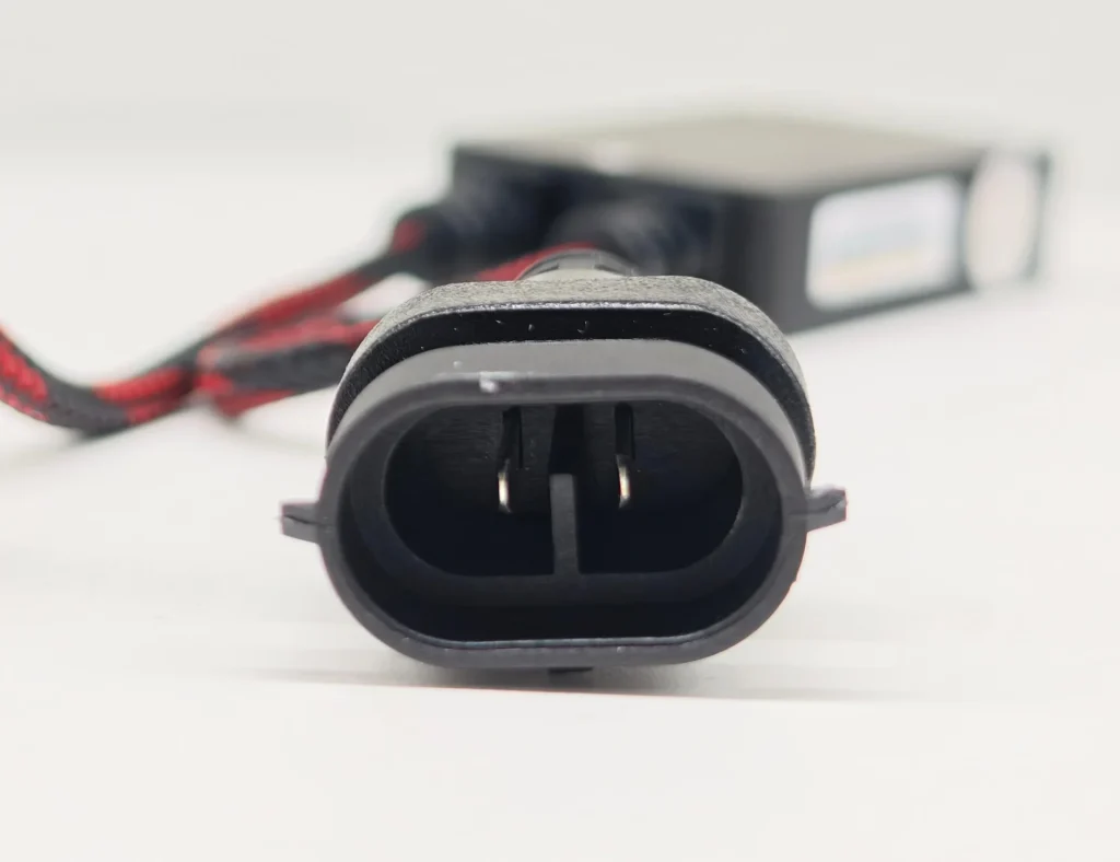
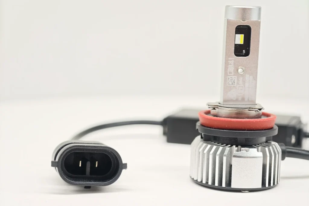
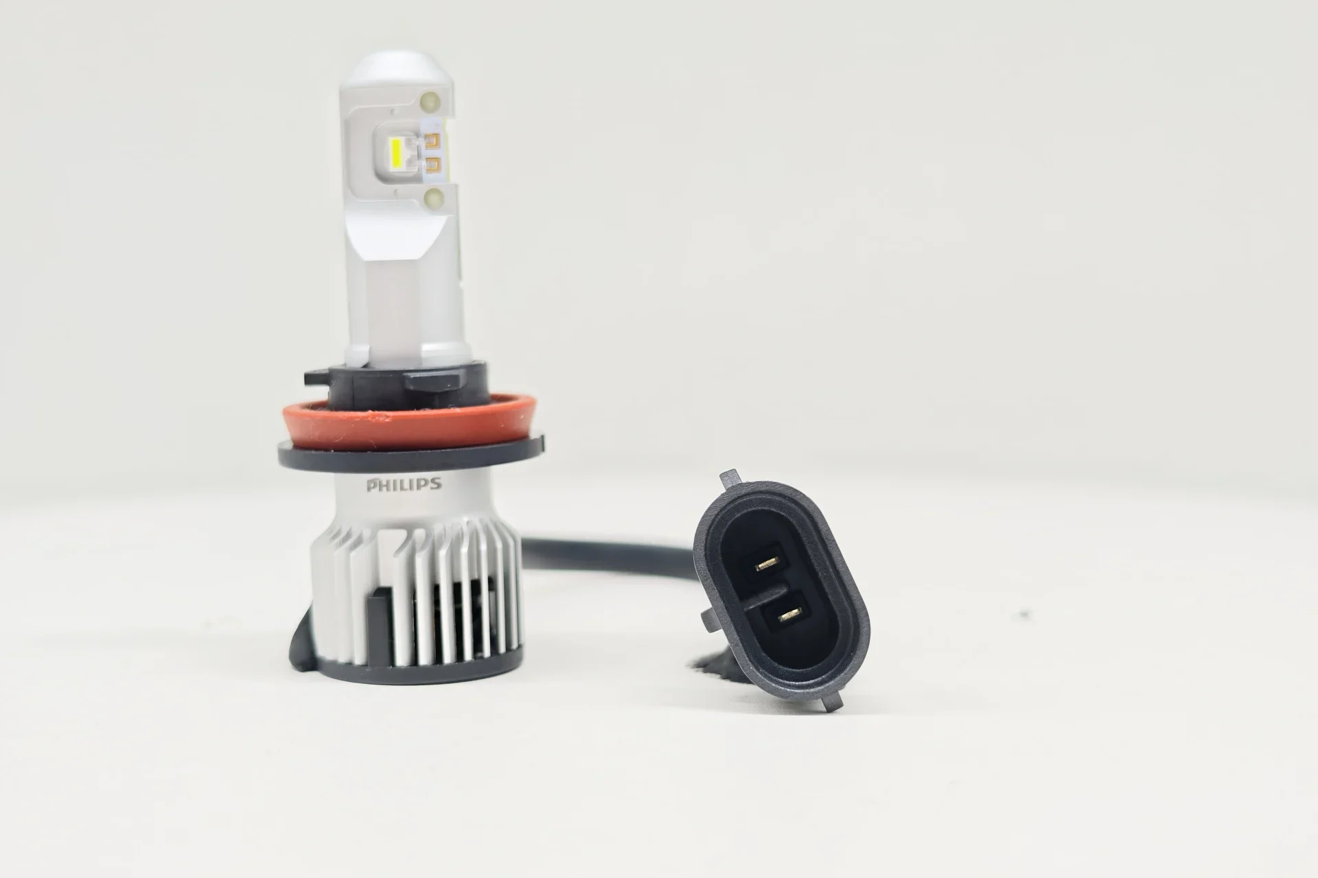
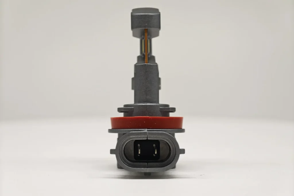
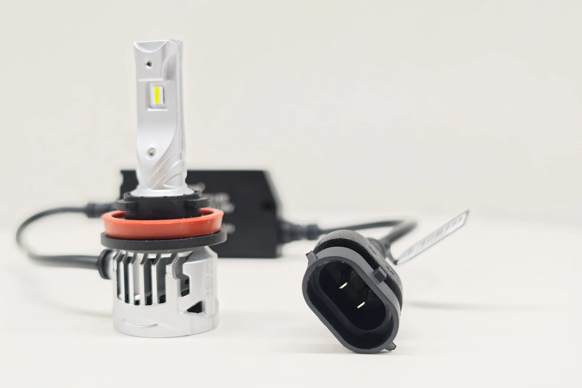
All five connector faces are oval and keyed, with two pins and a central divider. EB, OSRAM, Philips and Luxfighter place the connector on a lead. E4E fixes it directly to the side of the rear housing.
| H11 Connector Interface | |
|---|---|
| Comparison focus | Observation |
| Shared connector face | All five have a keyed oval face, two pins and a central divider. |
| Connection position | E4E fixes the connector to the rear housing; the other four place it on a lead. |
The visible connector format is shared across the five samples. The practical difference is the connection layout: the lead-mounted connectors can be positioned away from the lamp body, whereas E4E brings the connection directly to the rear housing.
3. PGJ19-2 base and locating features
The UNECE H11 LEDr category sheet specifies a PGJ19-2 cap. The IEC 60061 index identifies the PGJ19 cap drawing as sheet 7004-110-3 and the corresponding holder and connector drawing as sheet 7005-110-3. Together, these references define the category-specific mounting interface: the locating features establish orientation, and the base seats in the matching holder.
| H11 Base Standard Reference |
|---|
| Reference | What it specifies | Structural effect | Purpose |
|---|---|---|---|
| UN R37 and the H11 LEDr category sheet | H11 LEDr uses the H11 PGJ19-2 cap designation. | Defines the applicable H11 mounting interface. | Keeps the replacement source within the H11 category configuration. |
| IEC 60061-1, sheet 7004-110-3 | Defines the PGJ19 cap dimensions and locating features relevant to interchangeability, including the three-tab interface. | Controls the installation direction and the cap’s reference position in the holder. | Allows the cap to mate with the corresponding P |
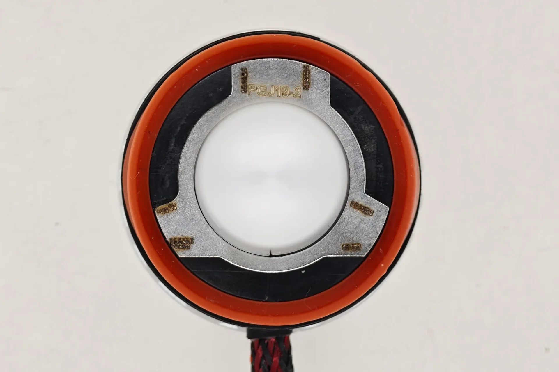
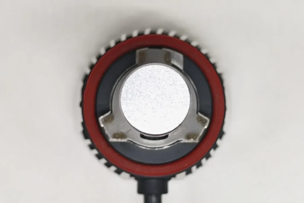
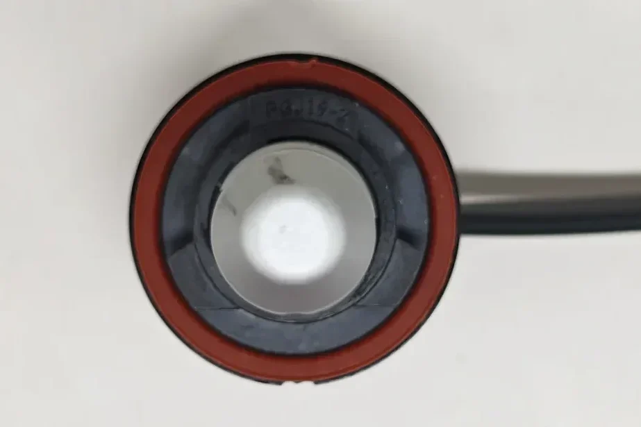
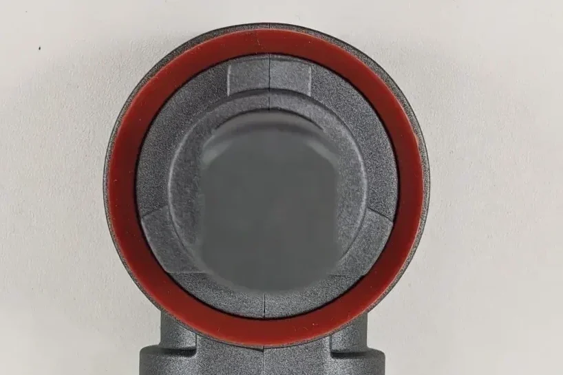
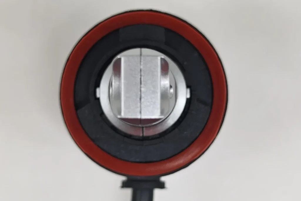
All five samples have a keyed mounting structure and a red sealing ring. EB, OSRAM and Philips use metal locating features. E4E uses moulded tabs on a universal multi-base arrangement, while Luxfighter has a black keyed H11 collar. EB, OSRAM and Philips therefore share the visible metal locating construction; E4E and Luxfighter use different base designs. For E4E’s interchangeable arrangement, the supplied H11 base and its corresponding approval documentation should be checked together.
4. Base Locating-Section Diameter
The UNECE H11 filament-category drawing, sheet H11/1 defines the reference axis through the centre of the 19 mm cap diameter. This places the diameter in the mounting geometry, where it establishes the centre used to locate the light source. The caliper photographs below measure the base locating section; the opposing LED emitting surfaces are measured separately in the next section.
| Why Measure Pillar Thickness | Main Impact | Relevance to Actual Headlight Performance |
|---|---|---|
| Light obstruction | The pillar can block part of the light emitted sideways or at oblique angles from the LED | An excessively thick pillar may block certain emission angles, resulting in incomplete angular light distribution or local dark areas |
| Heat transfer | The pillar is also part of the main thermal path from the LED chip to the heat sink | Its cross-section, material and internal structure affect how efficiently heat is transferred, influencing junction temperature and sustained light output |
| Structural strength and stability | The pillar provides mechanical support for the LED chip, PCB or substrate | An excessively thin pillar may reduce rigidity and increase the risk of displacement or deformation during assembly, vibration or thermal cycling |
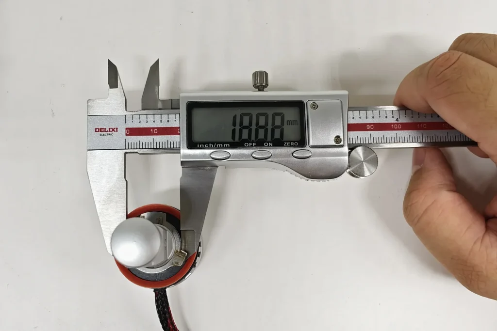
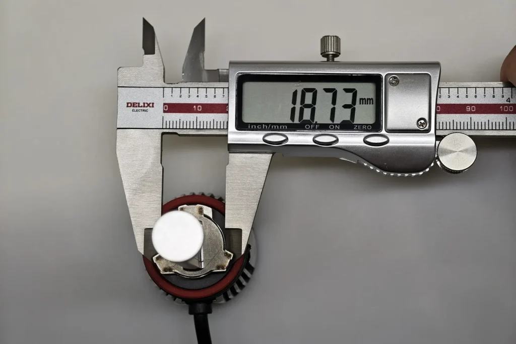
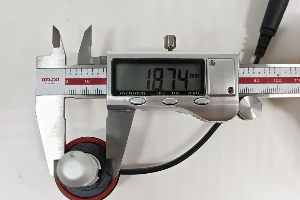
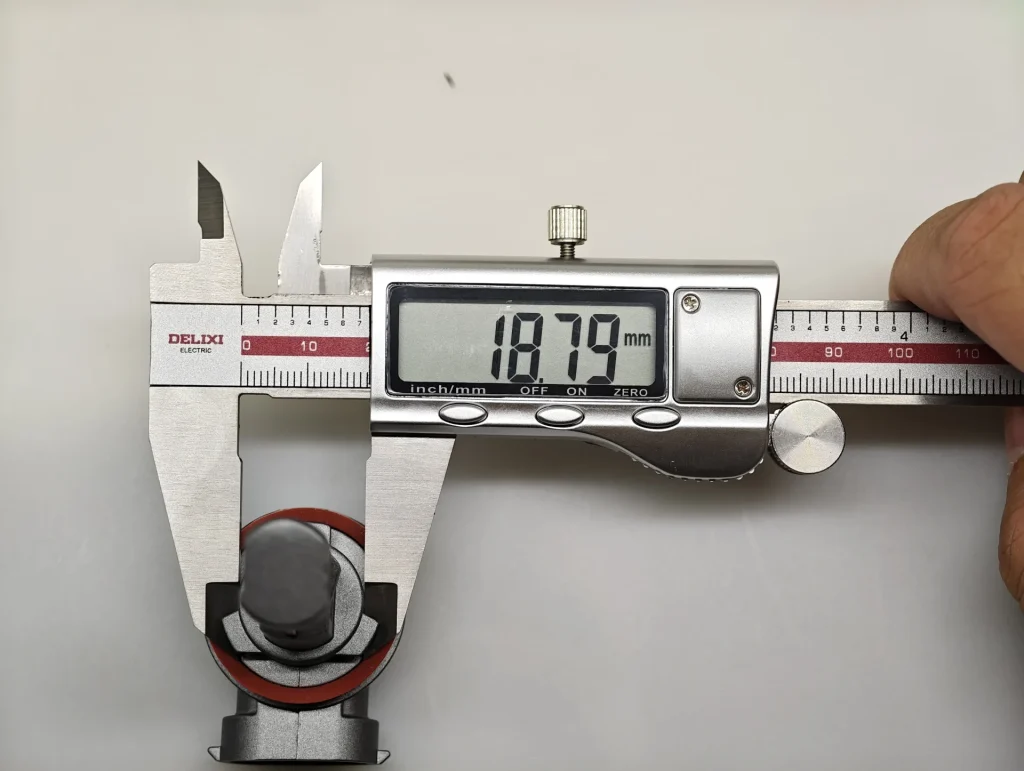
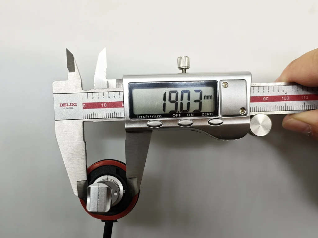
The readings run from 18.73 mm for OSRAM to 19.03 mm for Luxfighter. EB measures 18.88 mm, between the other four samples.
| Base Locating-Section Diameter | |
|---|---|
| Product | Measured diameter (mm) |
| EB | 18.88 |
| OSRAM | 18.73 |
| Philips | 18.74 |
| E4E | 18.79 |
| Luxfighter | 19.03 |
The five readings span 0.30 mm. The larger construction differences are the metal locating features, moulded tabs and keyed collar shown above; this diameter measurement records one part of that mounting interface.
5. Metal Retaining Spring
The IEC 60061 index lists the PGJ19 holder and connector system under sheet 7005-110-3. A metal retaining spring adds elastic pressure at the seated interface to help hold the lamp in position. It works alongside the locating features, which set orientation, and the sealing ring, which seals the joint.
| Retaining-Spring Standard Reference |
|---|
| Reference | What it specifies | Structural effect | Purpose |
|---|---|---|---|
| IEC 60061-2, PGJ19 holder and connector sheet 7005-110-3 | Defines the corresponding PGJ19 holder and connector interface, including the retaining arrangement used with the cap. | Affects whether the cap remains seated in its installed position. | Helps retain the light source after the keyed base has located it. |
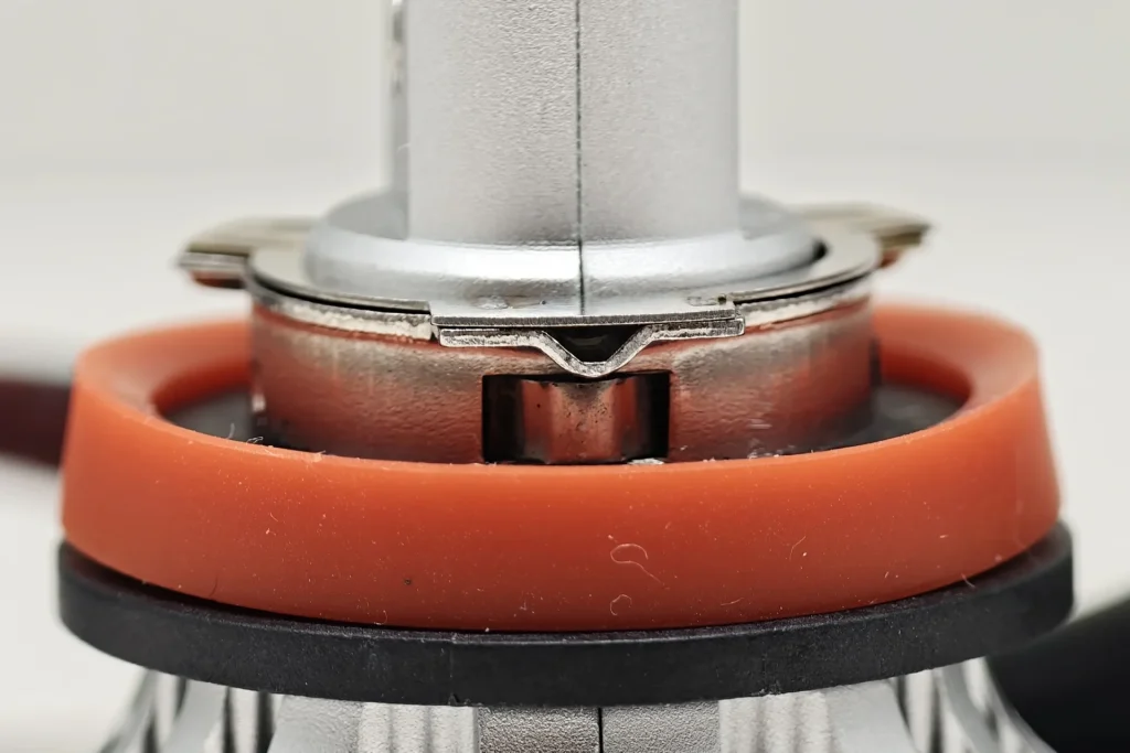
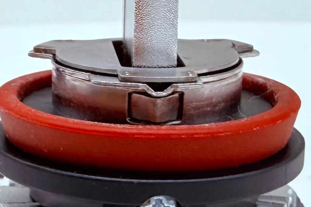
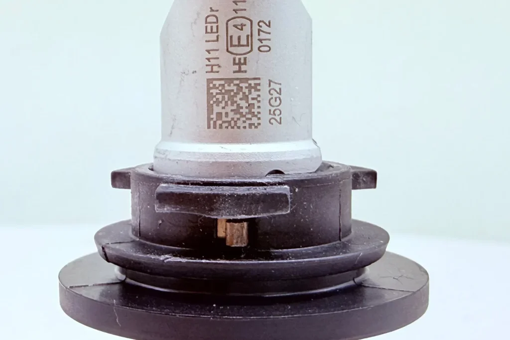
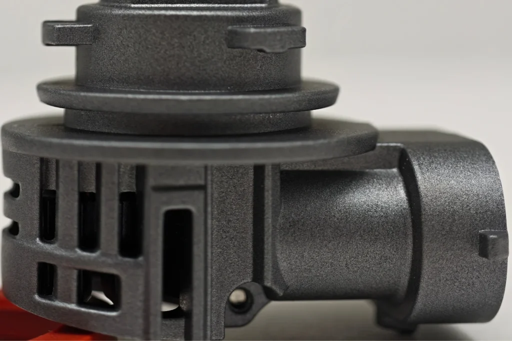
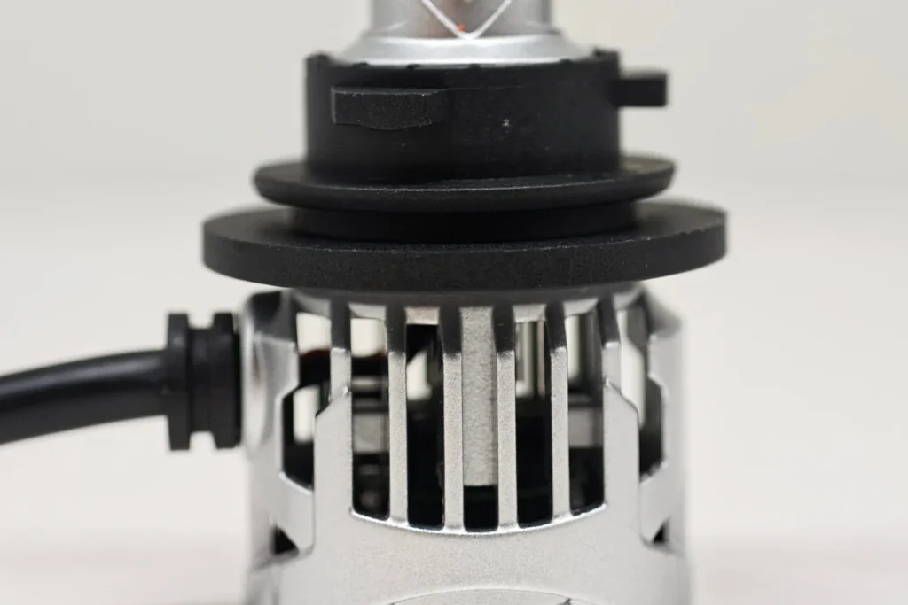
A separate metal retaining spring is visible beneath the flange on EB, OSRAM and Philips. The E4E and Luxfighter base photographs show no separate metal retaining spring.
| Metal Retaining Spring Comparison | |
|---|---|
| Observed construction | Samples |
| Separate metal retaining spring beneath the flange | EB, OSRAM and Philips |
| No separate metal retaining spring visible | E4E and Luxfighter |
EB, OSRAM and Philips share this spring-retained arrangement. EB therefore includes the same additional retaining component found on the two other metal-base samples, while E4E and Luxfighter lack a visible separate spring. The retaining arrangement belongs in the product specification alongside the base geometry.
Emitting Geometry and Box System
The mounting base establishes the lamp’s reference position. The next question is where the emitting surfaces sit relative to it. Close-ups reveal the phosphor layout, micrometer readings show the separation of the two emitting faces, and Box System photographs place the source inside a common reference frame.
1. Visible LED Emitting Structure
The phosphor window is the visible light-emitting surface. Physical gaps divide that surface into separate segments; internal divisions beneath a continuous window are recorded separately.
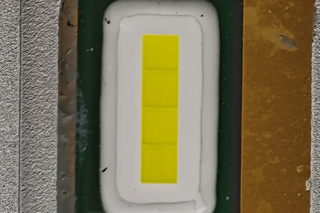
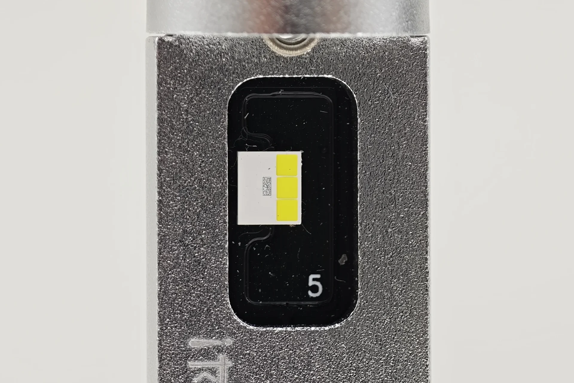
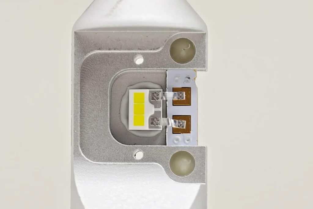
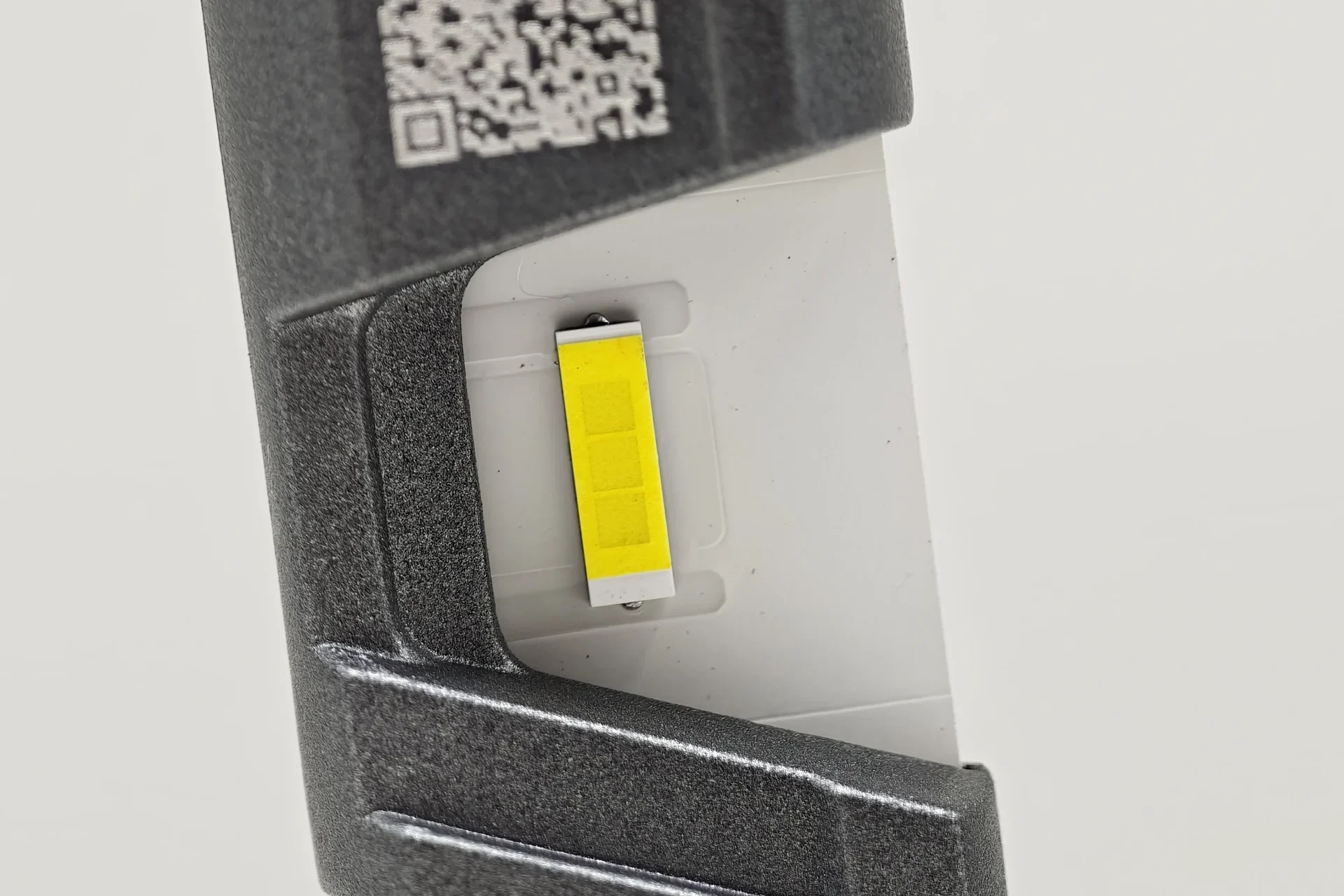
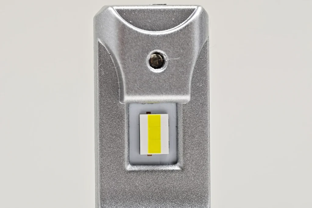
EB has one continuous rectangular phosphor window with four visible internal areas. E4E and Luxfighter also have continuous windows, each with three internal areas. OSRAM and Philips use three separate rectangular phosphor segments with two physical gaps.
| Visible LED Emitting Structure | |
|---|---|
| Comparison focus | Recorded difference |
| Continuous or separated phosphor surface | EB, E4E and Luxfighter have continuous rectangular windows. OSRAM and Philips have three separate phosphor segments with two physical gaps. |
| Divisions within the continuous window | EB shows four internal areas; E4E and Luxfighter show three. These internal divisions differ from the physical gaps on OSRAM and Philips. |
EB, E4E and Luxfighter provide an uninterrupted phosphor window, whereas OSRAM and Philips divide the emitting surface into three separate pieces. EB’s continuous construction is shared with two samples; the distance between its opposing faces supplies the next measured distinction.
2. Distance Between Opposing LED Emitting Surfaces
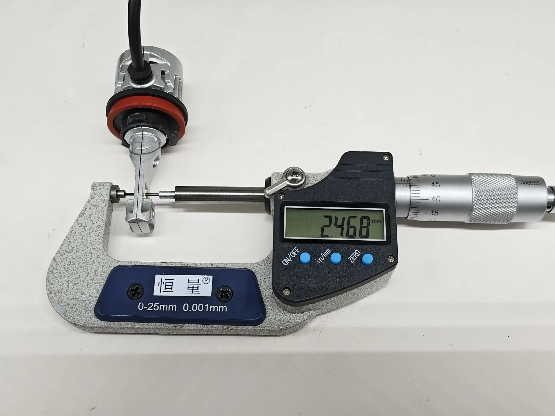
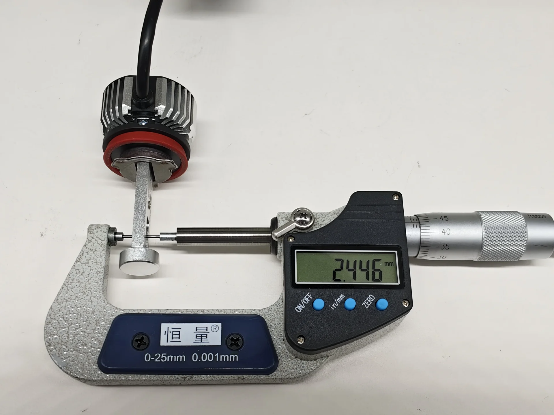
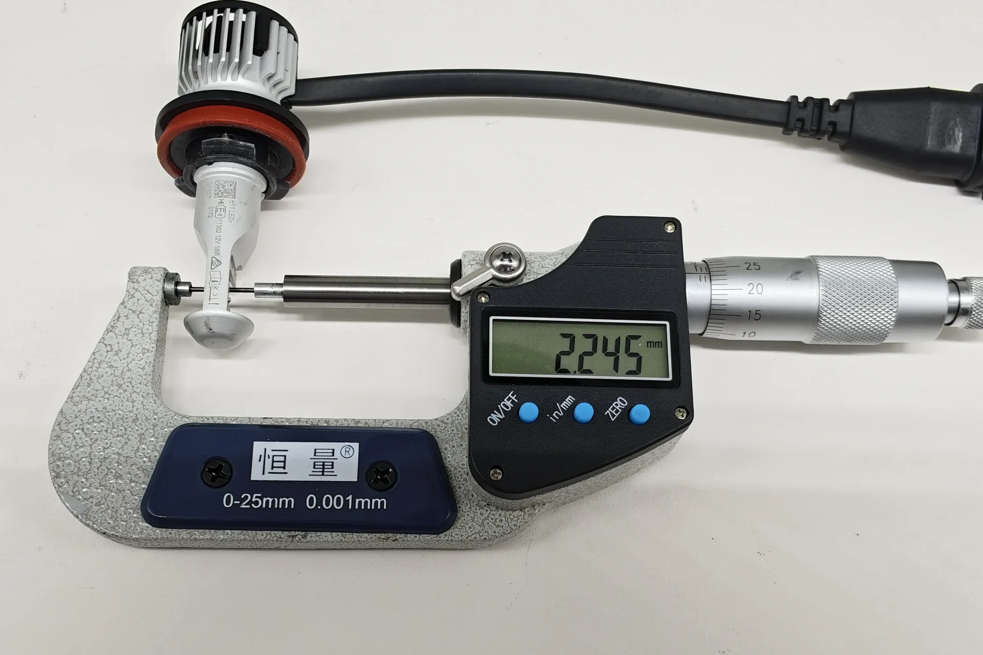
The UNECE H11 LEDr Configuration-2 reference calls this separation z and sets a maximum of 2.9 mm. It measures the distance from one outward-facing emitting surface to the opposite one, describing how compact the dual-sided source is.
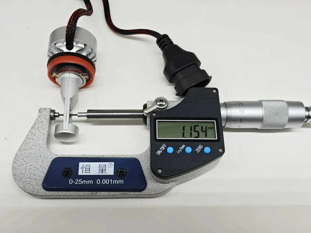
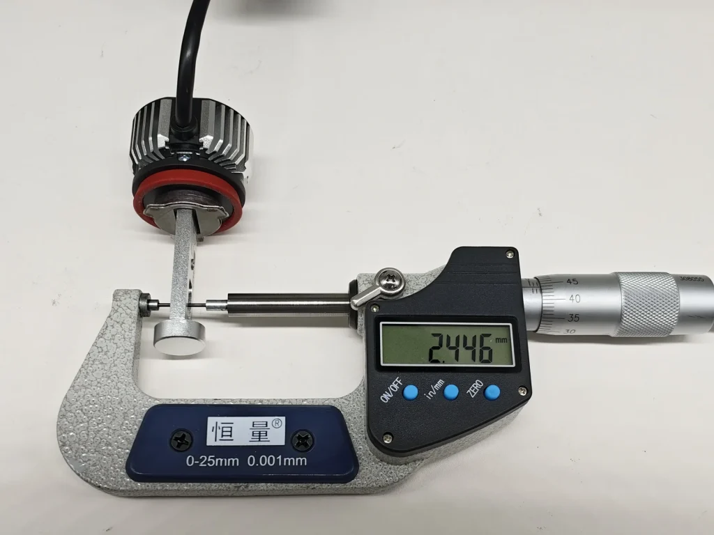
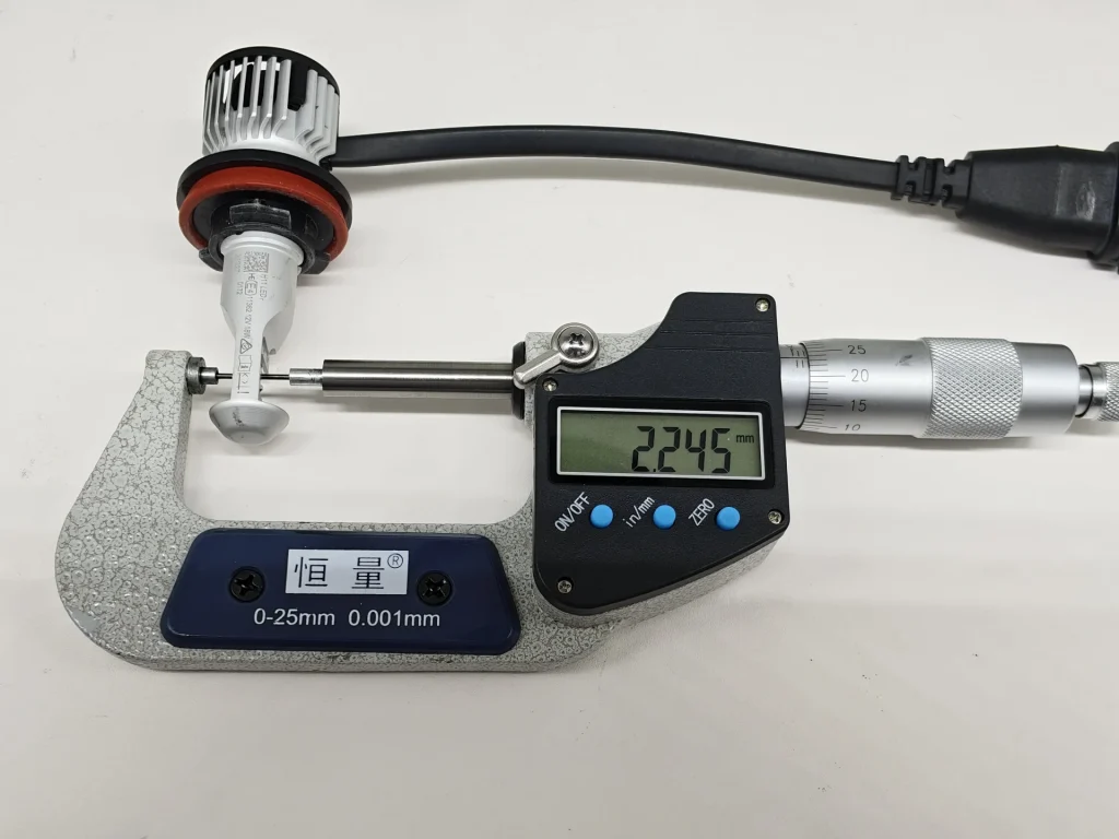
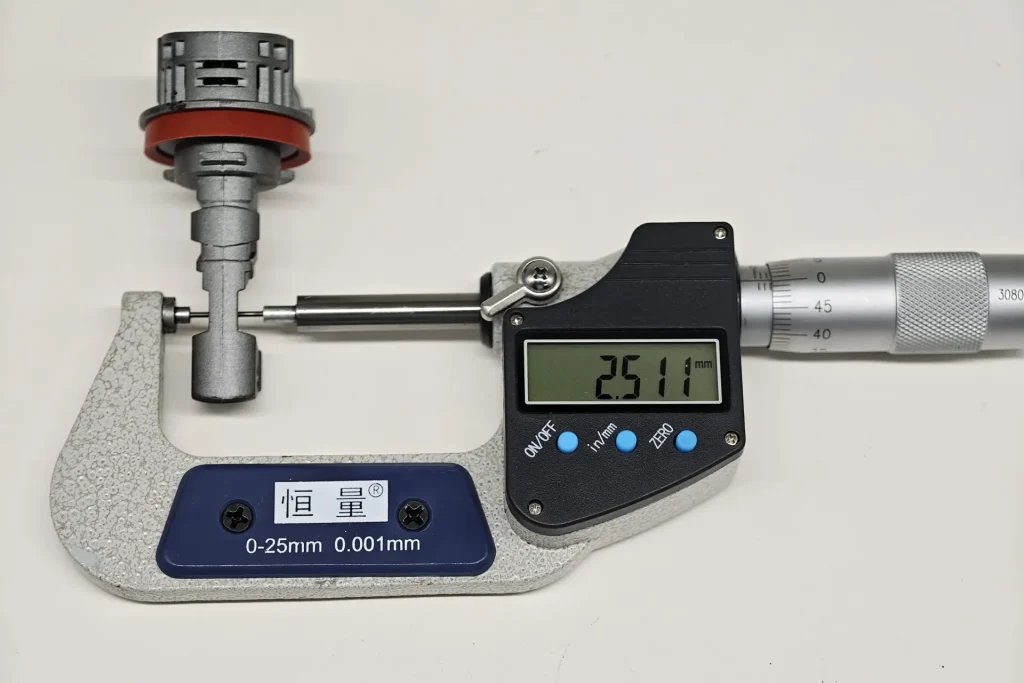
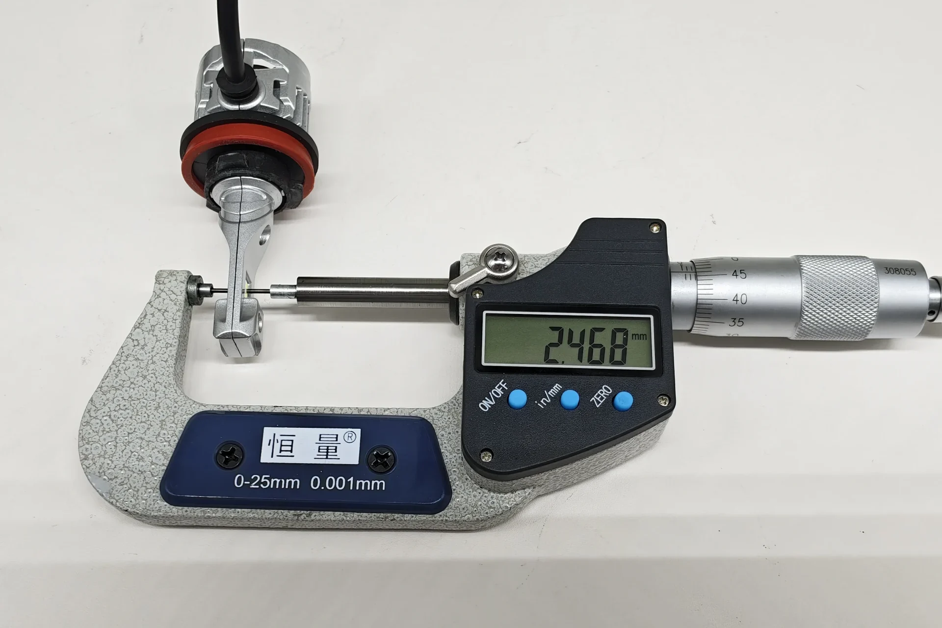
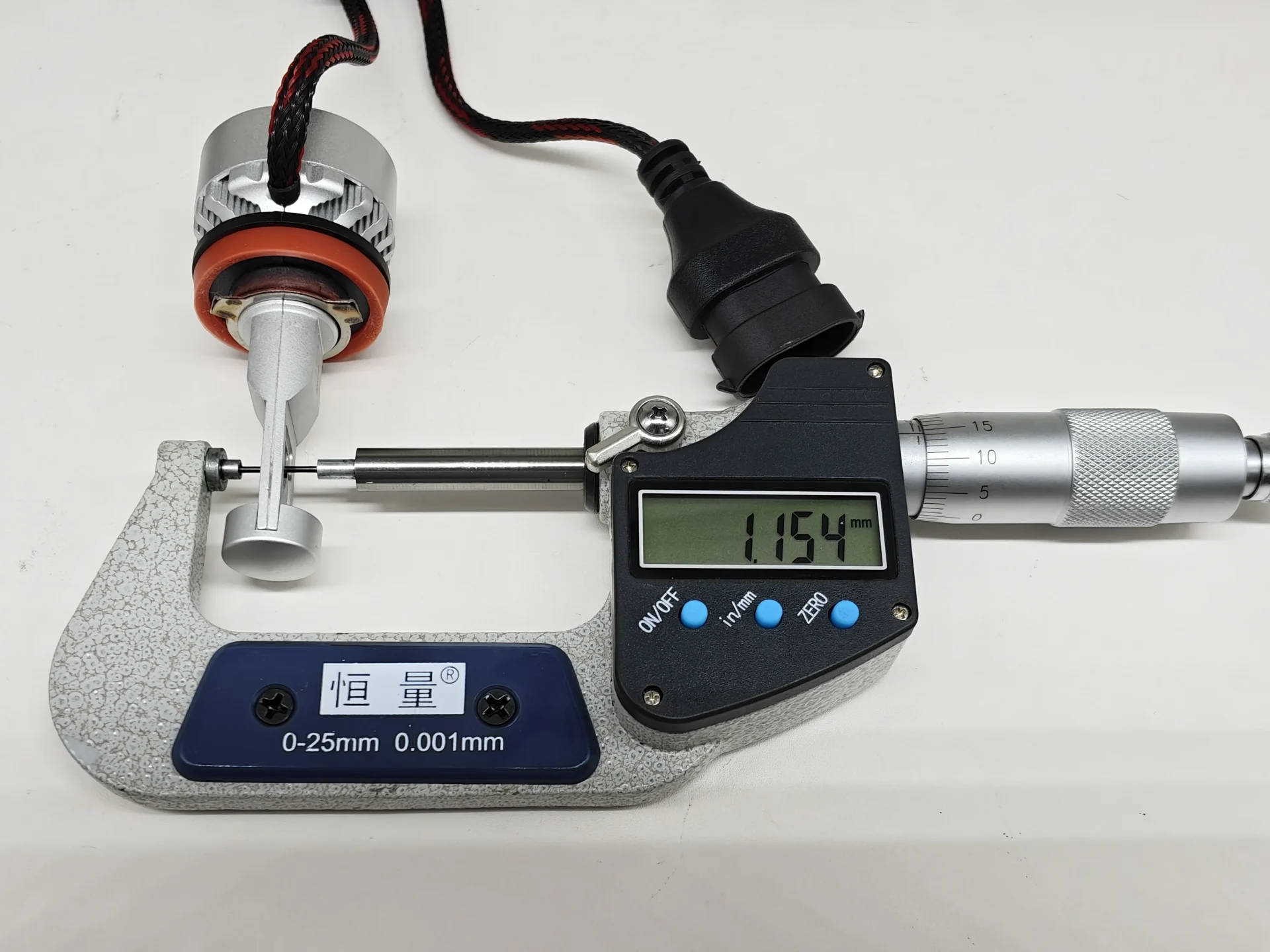
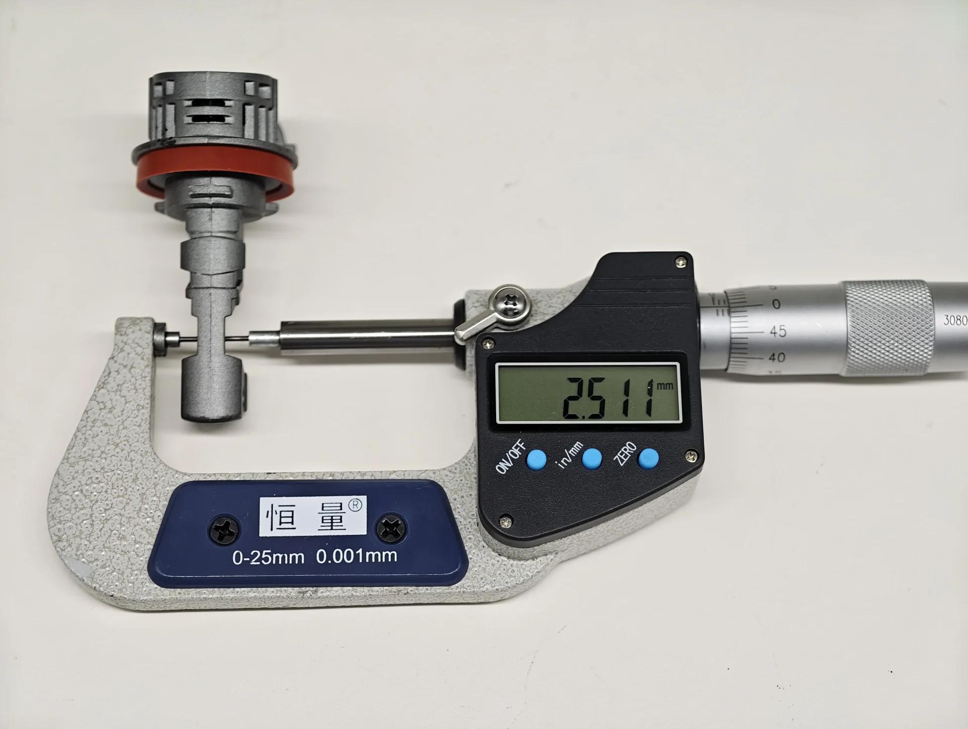
EB records 1.154 mm. The other four samples range from 2.245 mm for Philips to 2.511 mm for E4E, with OSRAM and Luxfighter between them.
| Opposing Emitting-Surface Distance | ||
|---|---|---|
| Product | Measured distance (mm) | Difference above EB (mm) |
| EB | 1.154 | — |
| OSRAM | 2.446 | 1.292 |
| Philips | 2.245 | 1.091 |
| E4E | 2.511 | 1.357 |
| Luxfighter | 2.468 | 1.314 |
All five recorded distances are below the 2.9 mm reference. EB has the thinnest dual-sided emitting geometry, measuring 48.60% to 54.04% less than the other samples. Philips is the next thinnest at 2.245 mm.
3. Box System: Reference Frame and Unlit Observation
The same UNECE category reference divides the main emitting region into A, B and C, with B1–B3 inside the core region B. It specifies flux proportions within these regions and a separate contrast check against D. This separates source positioning from light appearing outside the intended region.
| Box System Reference | ||
|---|---|---|
| Area | Specified reference | Purpose |
| A+B+C | At least 90% of total flux E in the specified viewing direction | Main emitting region |
| A | No more than 10% of A+B+C | Limits emission on one side of B |
| B | At least 72% of A+B+C | Core emitting region |
| B1 / B2 / B3 | Each at least 15% of B | Distribution within the core |
| C | No more than 22% of A+B+C | Limits emission beyond the other side of B |
| D | Contrast check against the main emitting region | Emission outside the main region |
These are luminous-flux and contrast requirements. The photographs below record visible position and coverage; they do not supply numerical flux ratios.
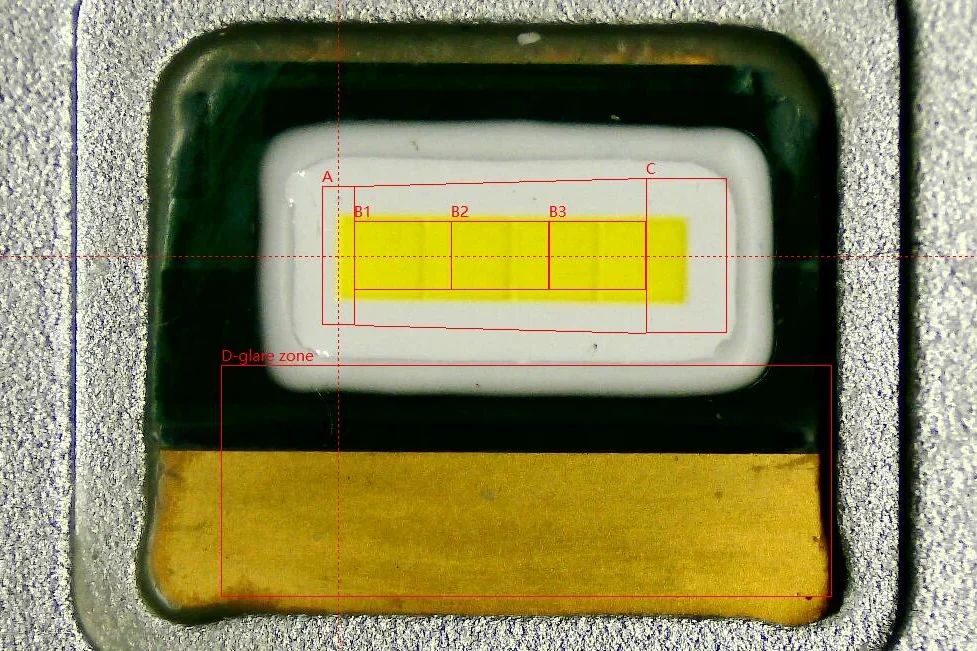
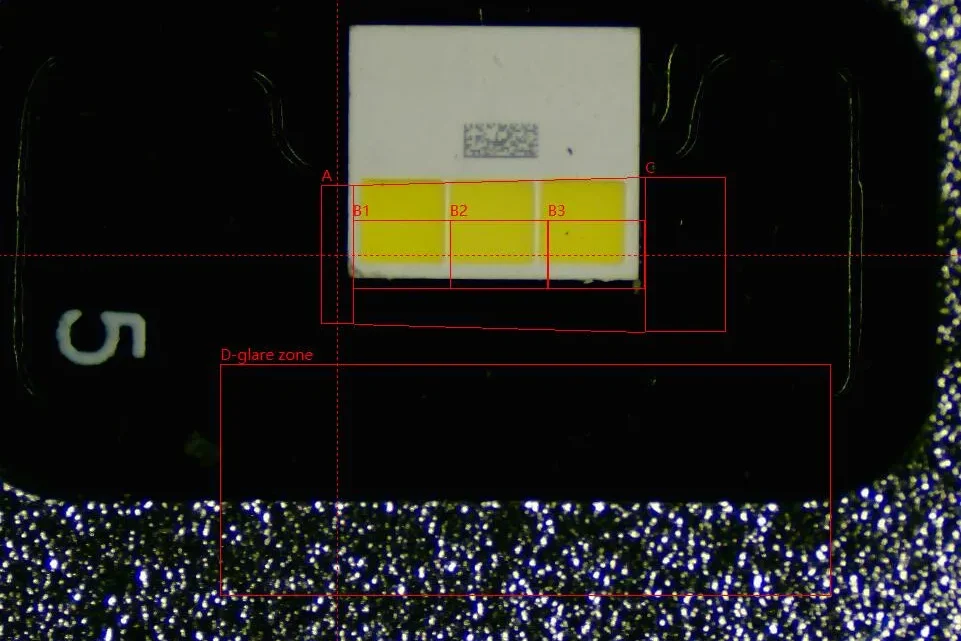
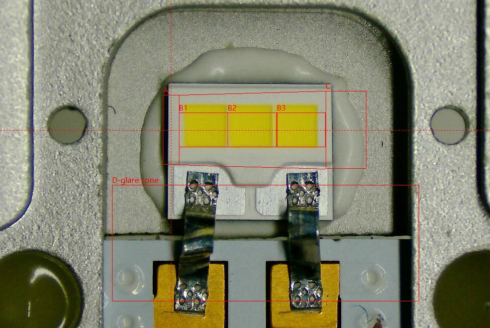
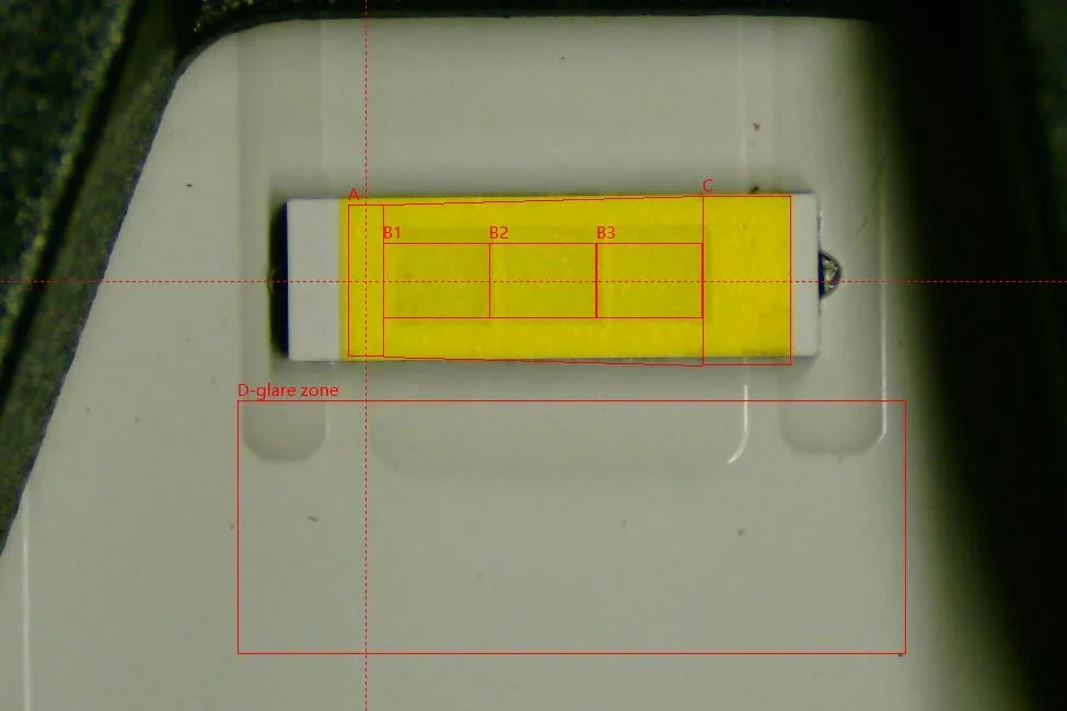
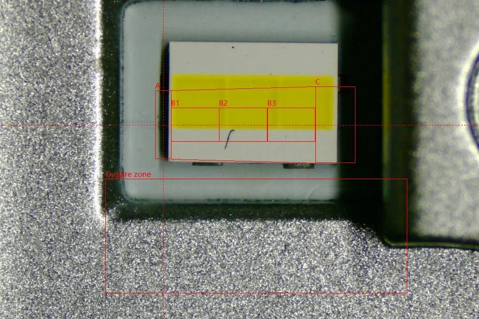
EB’s continuous strip crosses all three B subdivisions and covers more of their marked height than the higher-positioned OSRAM and Philips segments. E4E’s strip crosses B1–B3 and extends beyond the inner B rectangles. Luxfighter’s yellow window sits higher, with its upper portion above the A–C boundary and the lower B rectangles crossing the white package.
| Unlit Box System: Position Differences | |
|---|---|
| Reference area | Key observation |
| Height within B1–B3 | EB overlaps the marked vertical span. E4E extends above and below the inner B rectangles. OSRAM and Philips sit higher; Luxfighter leaves the lower B rectangles over the white package. |
| Upper A–C boundary | Luxfighter’s yellow window extends above the outer boundary. |
| Right-hand end | EB and OSRAM extend into C; Philips ends closer to the B/C boundary. |
The unlit records distinguish position from segmentation. EB combines a continuous strip with broad overlap through B, while E4E also spans the core region continuously. OSRAM and Philips sit higher, and Luxfighter shows the clearest extension above the outer boundary.
4. Box System with the Emitting Area Illuminated
Illuminating the samples reveals the bright band and light on surrounding surfaces that the unlit close-ups cannot show.
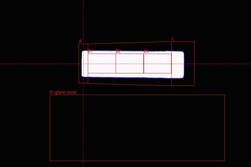
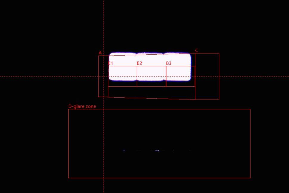
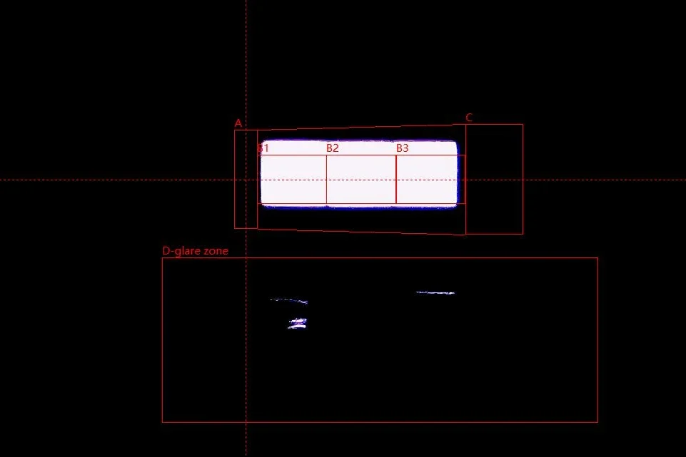
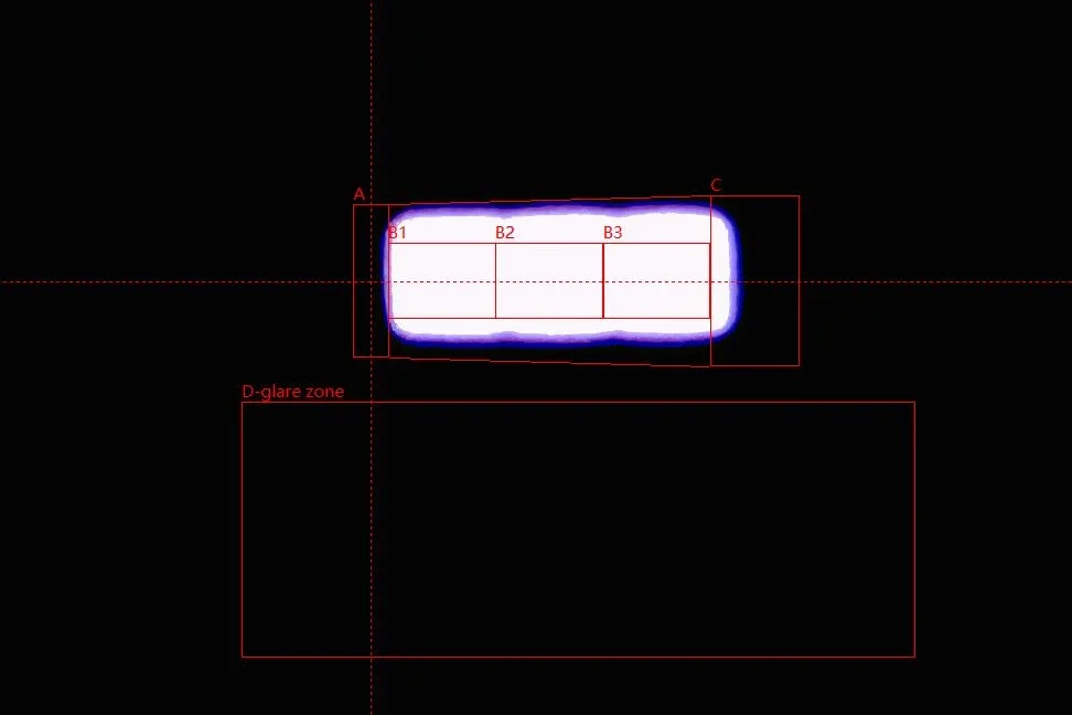
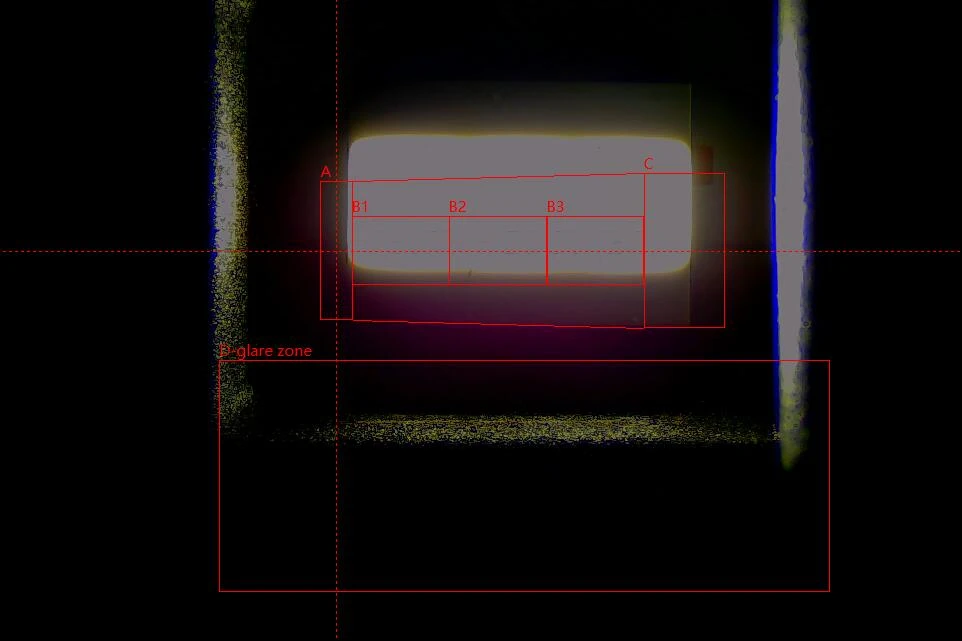
EB and E4E cover the marked height of B1–B3 and keep D visually dark. E4E has gently uneven bright edges with a violet fringe around the main band. OSRAM also keeps D dark, but its band sits higher. Philips shows isolated bright marks in D. Luxfighter extends above the upper boundary and shows a horizontal light band and bright surrounding edges in D.
| Illuminated Box System: Coverage and Surrounding Light | |
|---|---|
| Reference area | Key observation |
| B1–B3 coverage | EB and E4E cover the full marked height. OSRAM and Philips illuminate all three subdivisions with higher-positioned bands. Luxfighter leaves the lower B region less covered. |
| Bright perimeter | E4E has gently uneven edges and a violet fringe around the main band. Luxfighter extends above the upper A–C boundary. |
| Area D | Dark on EB, OSRAM and E4E. Philips has isolated bright marks; Luxfighter has a horizontal band, bright edges and diffuse light. |
EB combines full visible B-region coverage with a dark D region, a result also seen on E4E. OSRAM shares the dark D region but has a higher band position. EB’s strongest combination across this section is the continuous, well-centred bright band together with the smallest measured opposing-surface distance.
Beam Pattern and Illuminance
The source photographs show the emitting structure; the projected beam shows how that source works with the test headlamp. White-wall images reveal the cutoff, rainbow maps reveal hotspot shape, and the nine-point readings quantify the distribution.
1. White-Wall Beam Pattern
The horizontal cutoff and right-hand rise divide the main illuminated field from the area above it. The wall photographs show both the bright patch below the transition and the spread around that boundary.
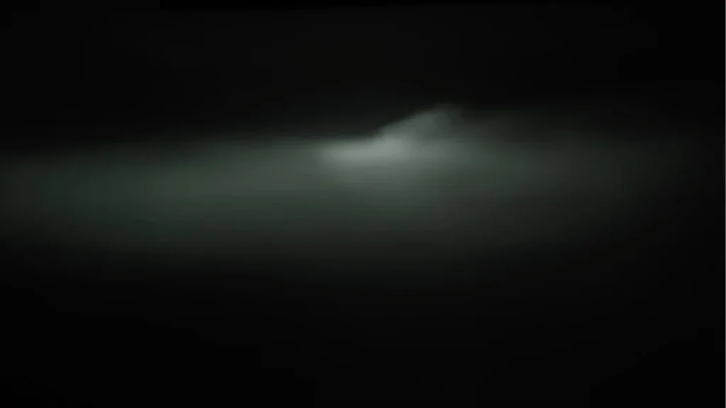
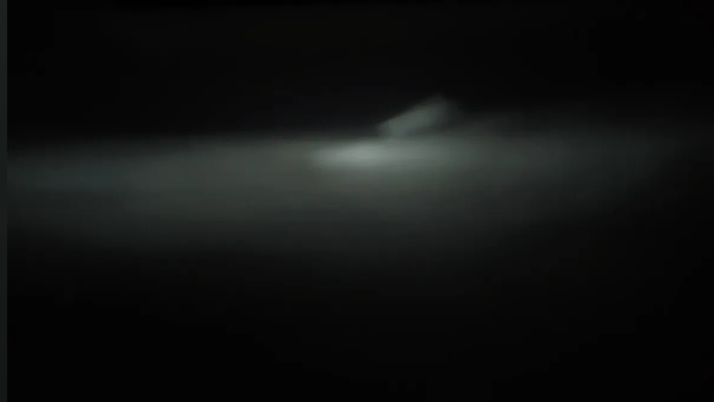
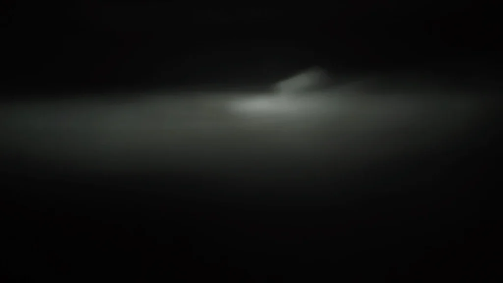
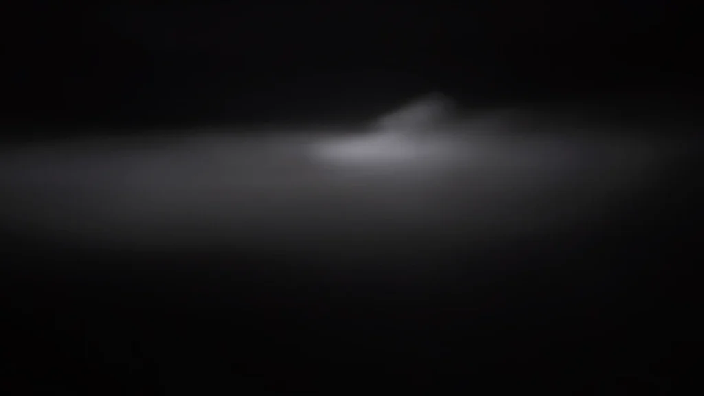
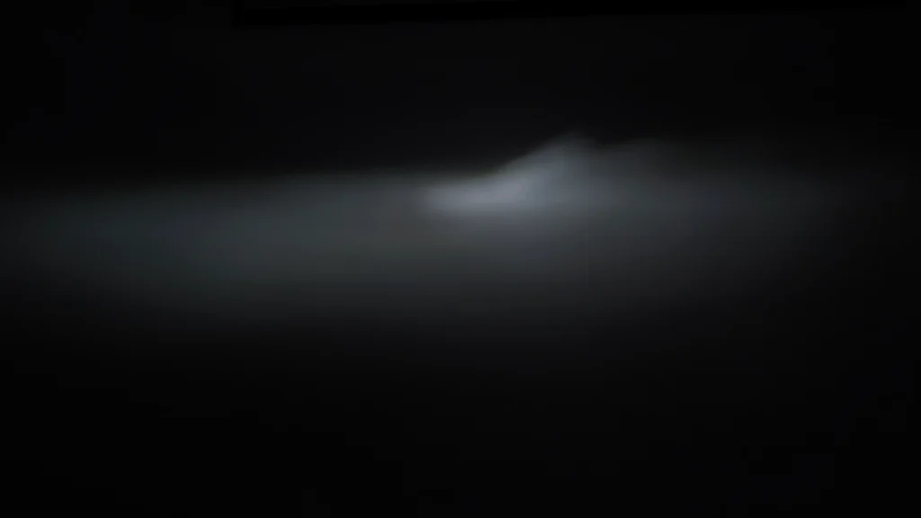
All five samples form a horizontal cutoff with a right-hand rise. EB places a compact bright patch below the transition. OSRAM, Philips and Luxfighter show more upward spread around the rising section, with haze visible on Philips. E4E has a pronounced rise and a broad surrounding field that fades towards the edges.
| White-Wall Beam: Main Visual Differences | |
|---|---|
| Comparison focus | Key observation |
| Basic cutoff | All five form a horizontal cutoff leading into a right-hand rise. |
| Light above the rise | EB leaves this area cleaner than OSRAM, Philips and Luxfighter; Philips also shows haze around the transition. |
| Bright-area shape | EB has a compact patch below the transition. E4E has a pronounced rise and a broader surrounding field; Luxfighter places its bright area higher. |
EB’s cleaner area above the rise accompanies its lower, more centrally aligned emitting band in the Box images. The higher bands on OSRAM, Philips and Luxfighter accompany greater upward spread. E4E retains broad illumination around the main patch. The main visual distinction is the shape and placement of the illuminated field.
2. Rainbow Map and Hotspot Distribution
The colour maps make the core’s outline and surrounding gradient easier to follow. The observations below compare those shapes; the illuminance table supplies the numerical output comparison.
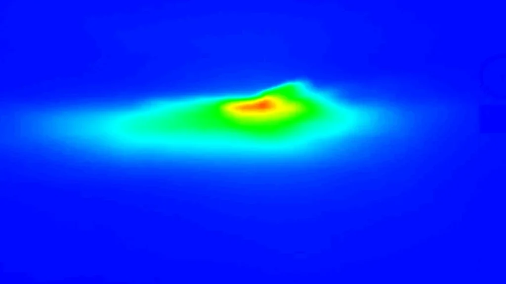
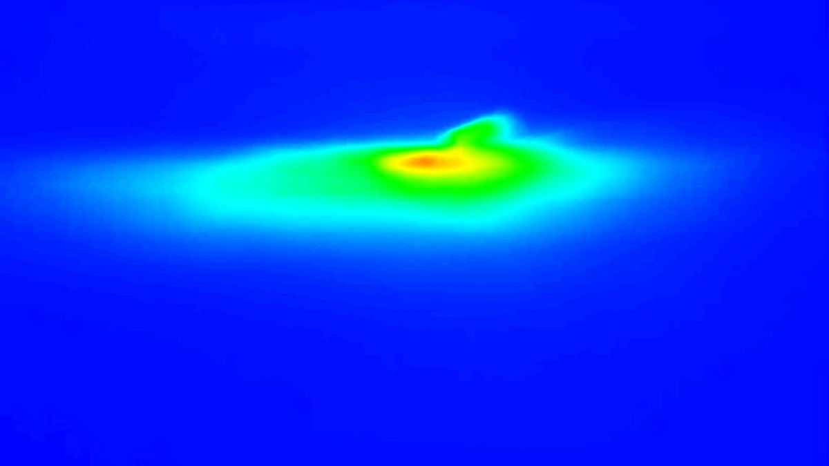
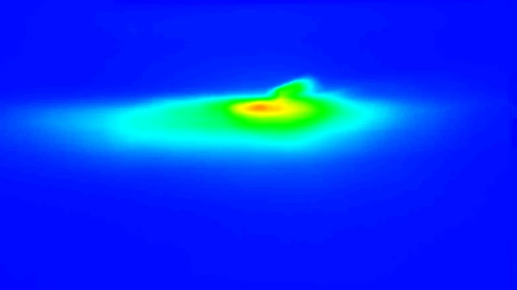
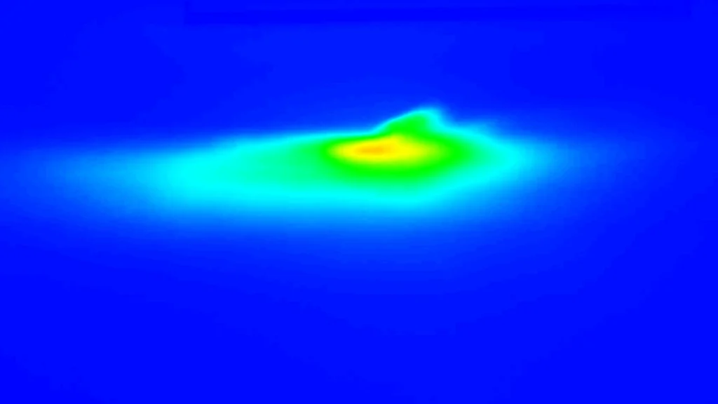
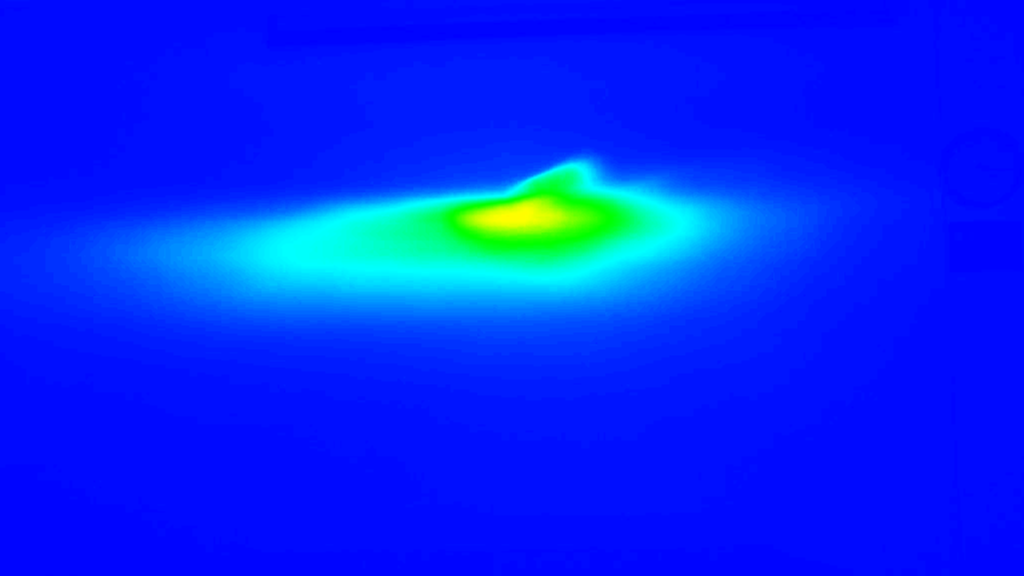
EB has a continuous red-orange core near the central-right transition, surrounded by a gradual yellow-green gradient. OSRAM’s core is narrower with an upward extension on the right. Philips forms a more elongated core extending rightward. E4E has a yellow-orange core inside a wider green-cyan surround, while Luxfighter’s broader yellow-green region extends upward and rightward.
| Rainbow Map: Hotspot Shape and Spread | |
|---|---|
| Comparison focus | Key observation |
| Core shape | EB has a fuller, continuous central-right core. OSRAM is narrower; Philips is more elongated towards the right. |
| Upward-right extension | Visible on OSRAM and across Luxfighter’s broader yellow-green region. |
| Surrounding field | EB shows a gradual yellow-green transition. E4E has a wider green-cyan surround around its elongated core. |
The upward extensions on OSRAM and Luxfighter accompany the higher emitting-band positions in their Box records. EB’s fuller central-right core accompanies broad overlap with B1–B3. E4E also covers B1–B3 and keeps D dark, yet produces a wider surrounding field.
3. Nine-Point Illuminance
B50L records light at the glare-control point above and left of the cutoff. The left, central and right-side points record local illumination, while EMAX is the peak. At 50L, more light is not automatically a better result because the point has both upper and lower regulatory limits in the prescribed test setup.
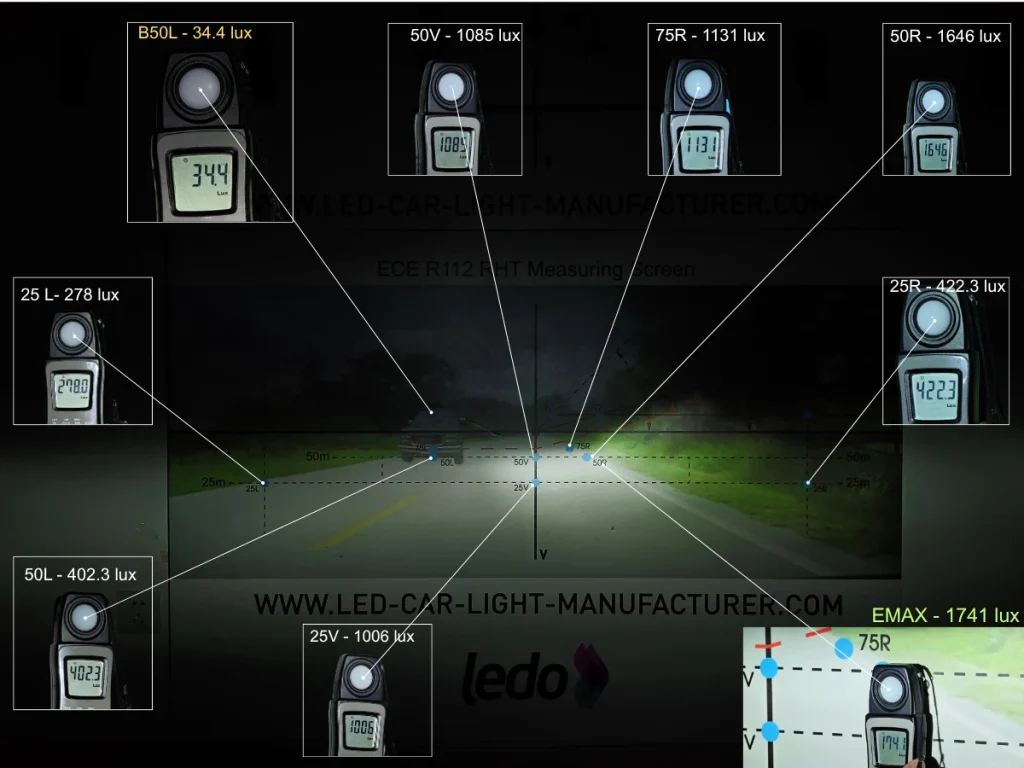
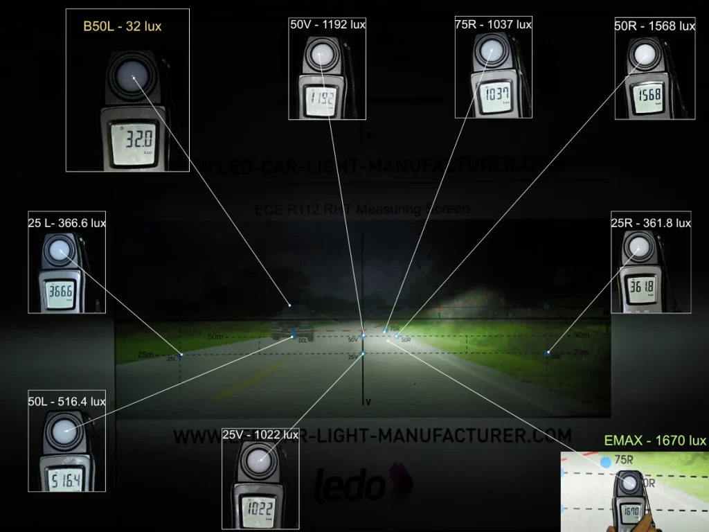
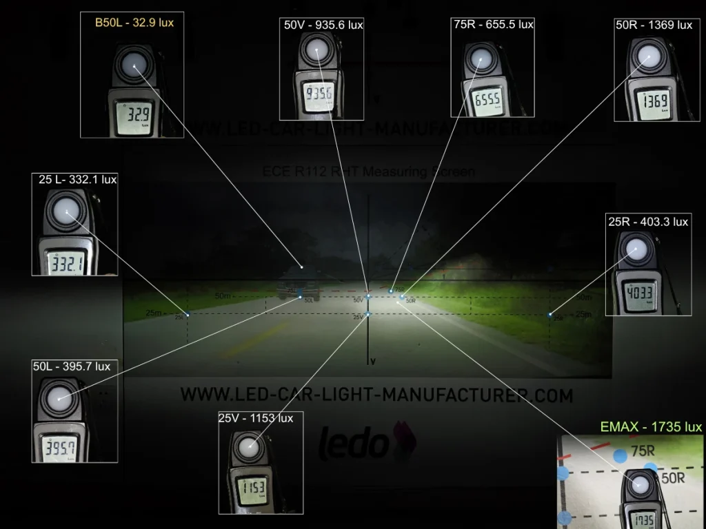
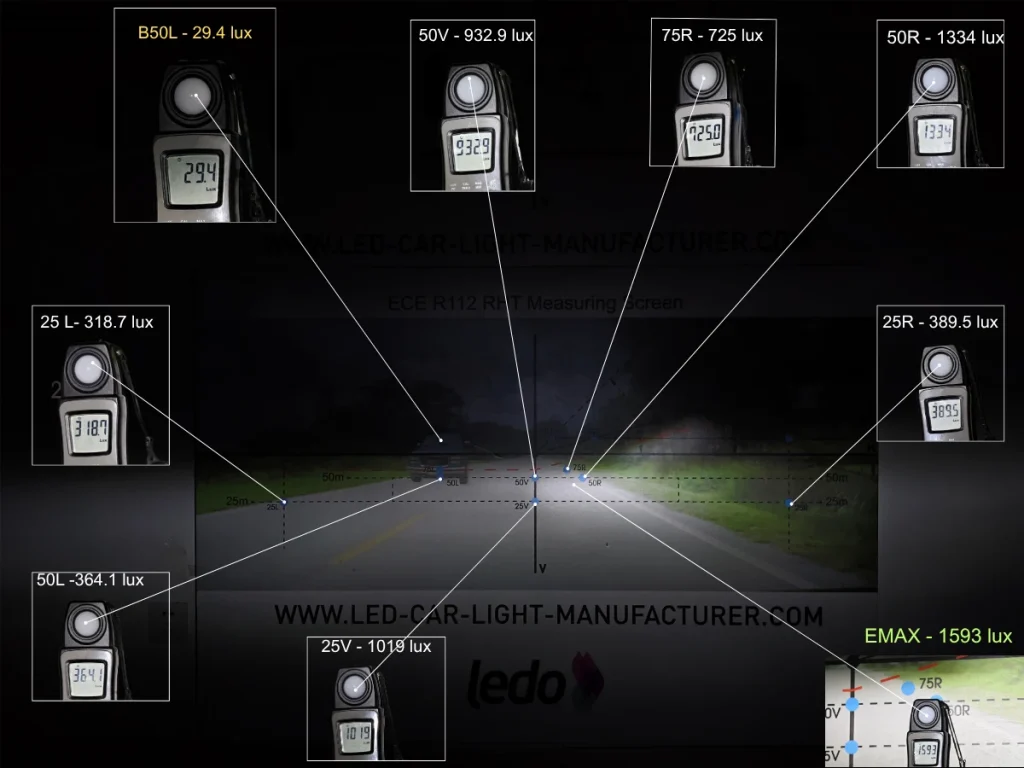
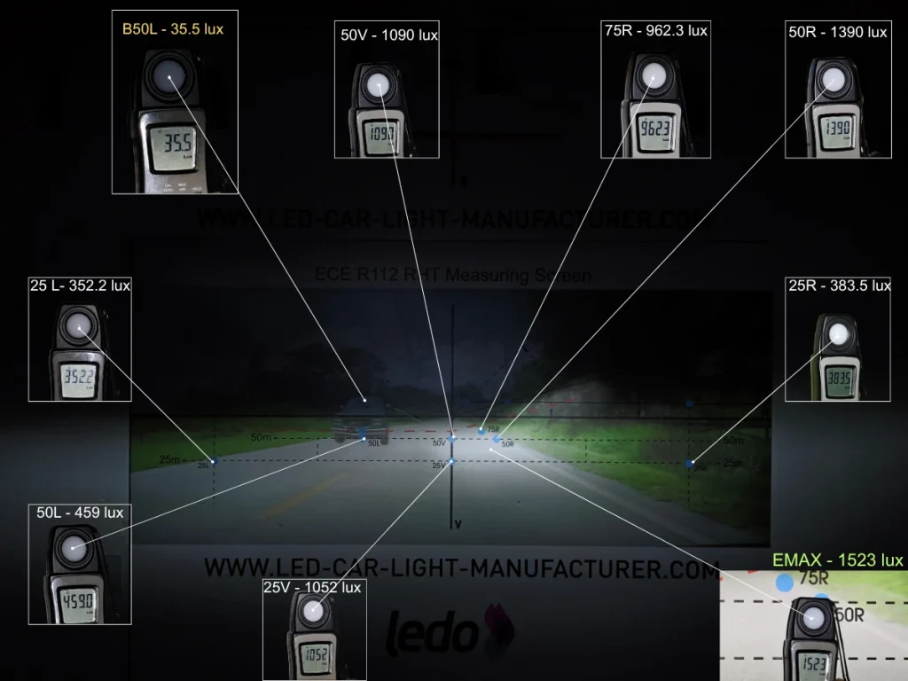
EB records the highest EMAX and all three right-side readings. OSRAM is highest at 25L, 50L and 50V, while Philips is highest at 25V. E4E has the lowest B50L reading.
| Complete Nine-Point Illuminance Data — Lux | |||||
|---|---|---|---|---|---|
| Point | EB | OSRAM | Philips | E4E | Luxfighter |
| B50L | 34.4 | 32.0 | 32.9 | 29.4 | 35.5 |
| 25L | 278 | 366.6 | 332.1 | 318.7 | 352.2 |
| 50L | 402.3 | 516.4 | 395.7 | 364.1 | 459 |
| 50V | 1,085 | 1,192 | 935.6 | 932.9 | 1,090 |
| 25V | 1,006 | 1,022 | 1,153 | 1,019 | 1,052 |
| 75R | 1,131 | 1,037 | 655.5 | 725 | 962.3 |
| 50R | 1,646 | 1,568 | 1,369 | 1,334 | 1,390 |
| 25R | 422.3 | 361.8 | 403.3 | 389.5 | 383.5 |
| EMAX | 1,741 | 1,670 | 1,735 | 1,593 | 1,523 |
B50L is an important reference point for glare control, and E4E recorded the lowest reading among the five products. However, the maximum difference across all five samples was only 6.1 lux, indicating that the overall variation at this point was relatively small.OSRAM places more measured light through the centre-left, Philips records 1,153 lux at 25V, and E4E reduces B50L to 29.4 lux.EB’s advantage extends across the right-side field rather than resting on one peak: it leads 25R, 50R and 75R. Its 1,741 lux peak is only 6 lux above Philips, so the larger distinction between those two samples is distribution.
Temperature and Fan Noise
1. Emitting-Area Surface Temperature After 30 Minutes
The temperature record shows local surface heat at the LED emitting area after the same operating period. It is a surface measurement, not an LED junction-temperature measurement.
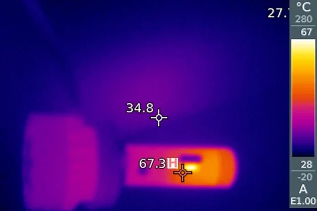
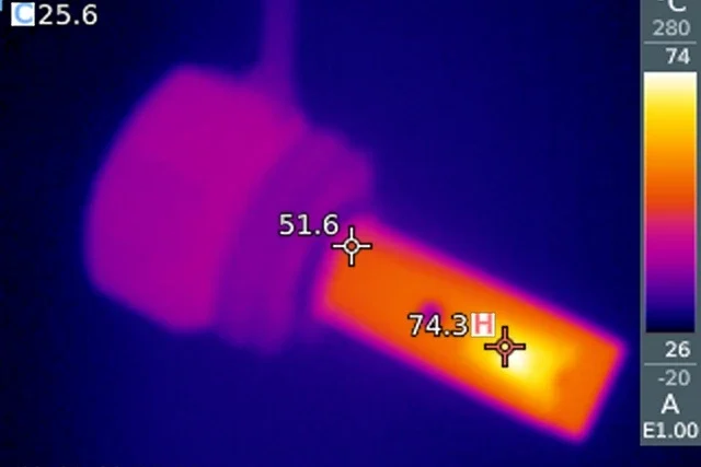
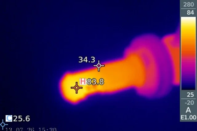
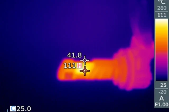
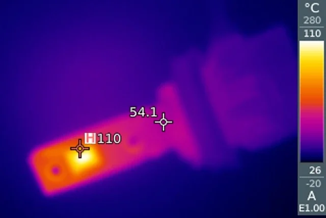
EB records 67.3°C, followed by OSRAM at 74.3°C and Philips at 83.8°C. Luxfighter reaches 110°C and E4E 111°C.
(The maximum temperature refers only to the measured surface temperature of the LED emitting area after 30 minutes, not the LED junction temperature.)
| Emitting-Area Surface Temperature | ||
|---|---|---|
| Product | Surface temperature after 30 minutes (°C) | Difference above EB (°C) |
| EB | 67.3 | — |
| OSRAM | 74.3 | 7.0 |
| Philips | 83.8 | 16.5 |
| E4E | 111 | 43.7 |
| Luxfighter | 110 | 42.7 |
EB has the lowest measured surface temperature, 7.0°C below the next-lowest sample, OSRAM. Its largest gaps are against E4E and Luxfighter, both more than 42°C higher under the recorded conditions.
2. Fan Noise at 3.5 cm
Sound was measured at the same close distance from each cooling fan. This compares fan noise on the test bench, separately from the temperature measurement.
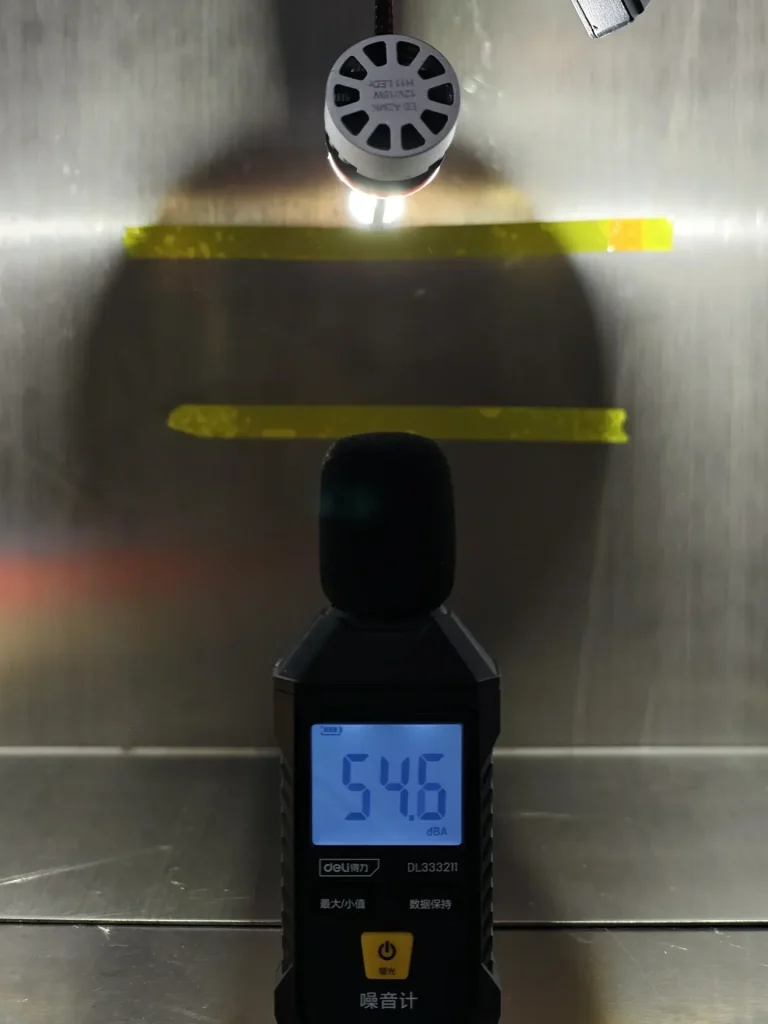
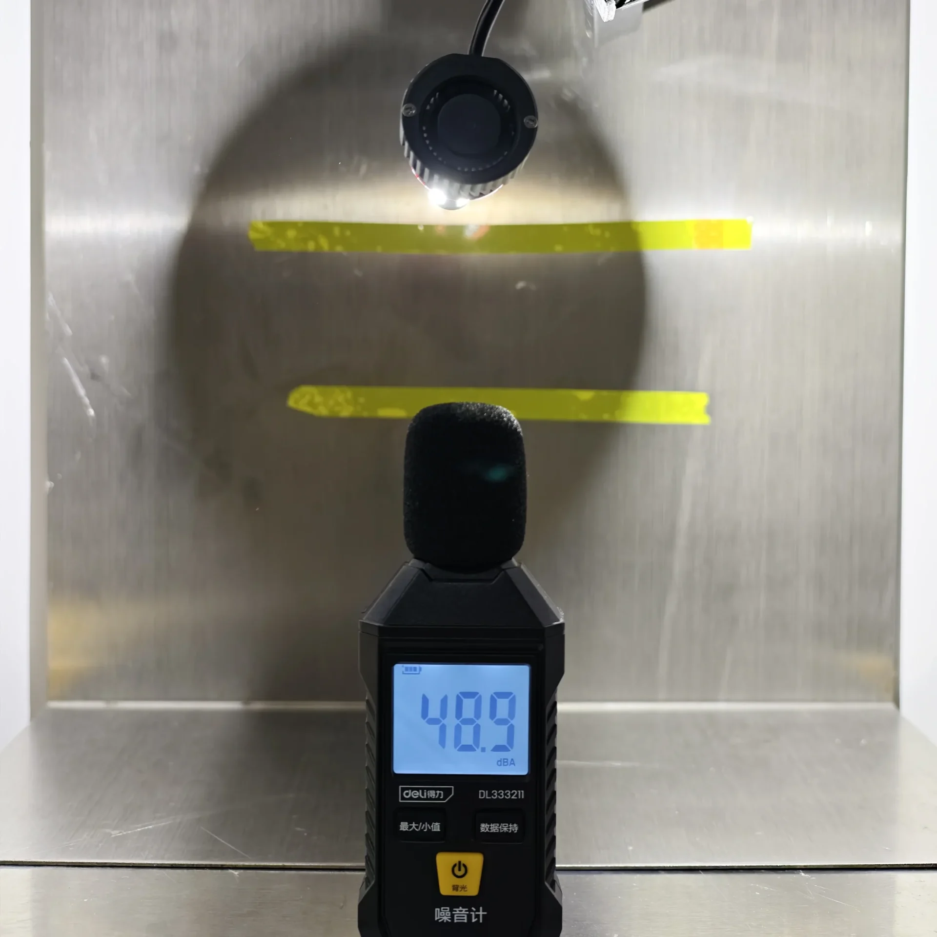
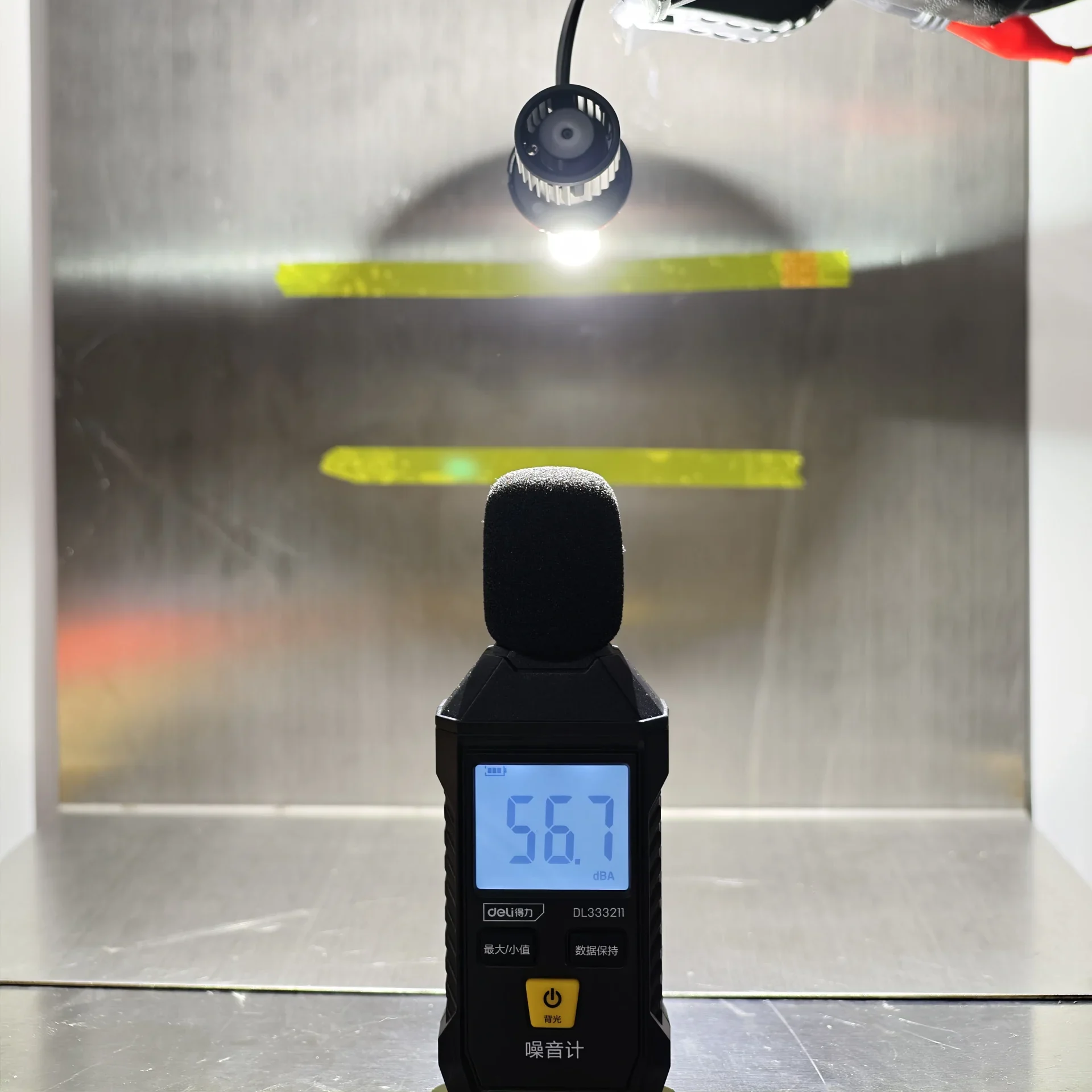
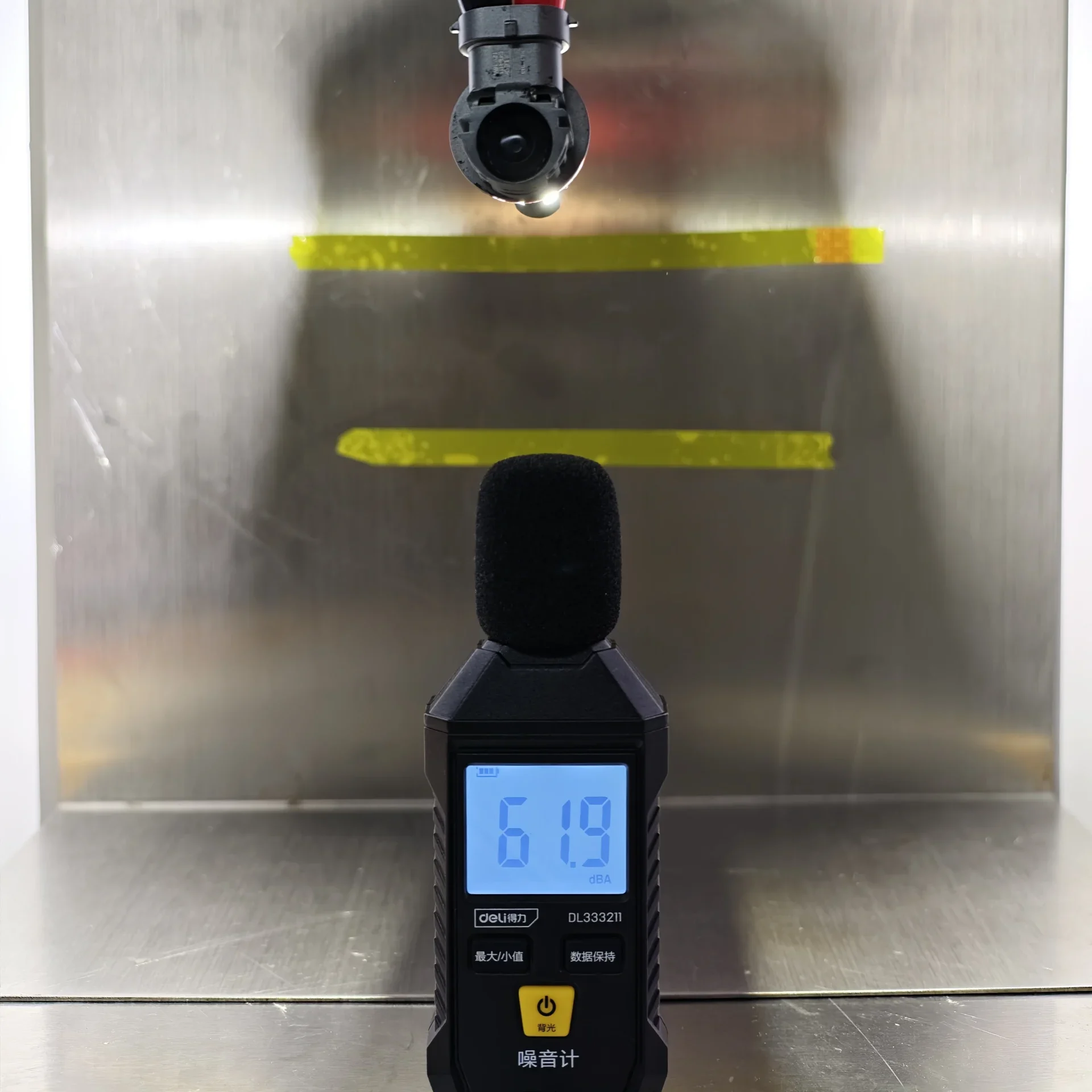
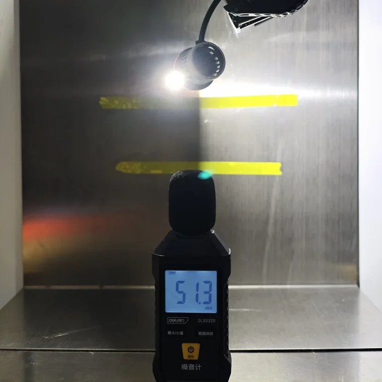
OSRAM records the lowest level at 48.9 dBA, followed by Luxfighter at 51.3 dBA. EB is in the middle at 54.6 dBA; Philips and E4E record 56.7 and 61.9 dBA.
| Fan Noise at 3.5 cm | |
|---|---|
| Product | Recorded sound level (dBA) |
| EB | 54.6 |
| OSRAM | 48.9 |
| Philips | 56.7 |
| E4E | 61.9 |
| Luxfighter | 51.3 |
OSRAM stands out for the quietest measured fan, 5.7 dBA below EB. Luxfighter is also quieter than EB by 3.3 dBA. EB combines the lowest emitting-area surface temperature with less fan noise than Philips and E4E.
Overall Findings
- E4E’s compact packaging and integrated rear connection reduce storage space and the number of loose components to arrange. Its lower B50L reading also means less light at the measured glare-control point. The trade-offs are weaker right-side illumination, higher surface temperature and louder fan operation. Its universal base requires configuration-specific compliance verification, while the absence of a separate metal retaining spring and packaging hanging feature adds considerations for mounting specifications and retail display.
- OSRAM combines organised retail packaging, direct peg-hook display and metal spring retention with the quietest fan in the comparison. Its distribution places more light through the left and central reference points, while its emitting-area surface temperature is the second-lowest. However, the larger, heavier package adds storage and packaging-weight demands. Compared with EB, the beam shows more upward spread around the rise and less illumination at the right-side points.
- Philips combines metal locating features and spring retention with fewer visible external components. Its main optical strengths are strong near-centre illumination and peak output close to EB’s. That peak is not matched by equally strong right-side readings, particularly at 75R. Haze around the rising cutoff and isolated bright marks in Area D are further weaknesses in the visual record. It also runs hotter and produces more fan noise than EB.
- Luxfighter offers lighter packaging and quieter fan operation than EB, together with more measured light through the centre-left field. Its weaknesses are less controlled visible emission around the source, greater upward beam spread and lower right-side and peak illumination. The quieter fan accompanies a substantially higher emitting-area surface temperature. Its package also lacks direct peg-hook support, and the tested base has no separate metal retaining spring.
- EB’s compact packaging saves storage space, while its hanging feature lets retailers place the box directly on peg-hook displays without an additional hanger. Its dedicated H11 base and metal retaining spring help position and hold the lamp, giving brands and purchasing teams clear mounting features to include in their product specifications. Braided leads add a protective covering, and the narrow external driver keeps the separate module slim. The beam combines a clean cutoff area, a well-defined hotspot and strong right-side illumination, giving distributors concrete, test-backed strengths to explain to customers. Packaging weight and fan noise leave us room for further improvement. Overall, EB brings together practical packaging, dedicated mounting construction and well-controlled light distribution.
Author: Jack Liu, Co-founder and Product Director, LEDOAUTO
Technical review: LEDOAUTO Engineering Team
Test source: LEDOAUTO, manufacturer of the EB sample
Last updated: September 7, 2026
Frequently Asked Questions
References
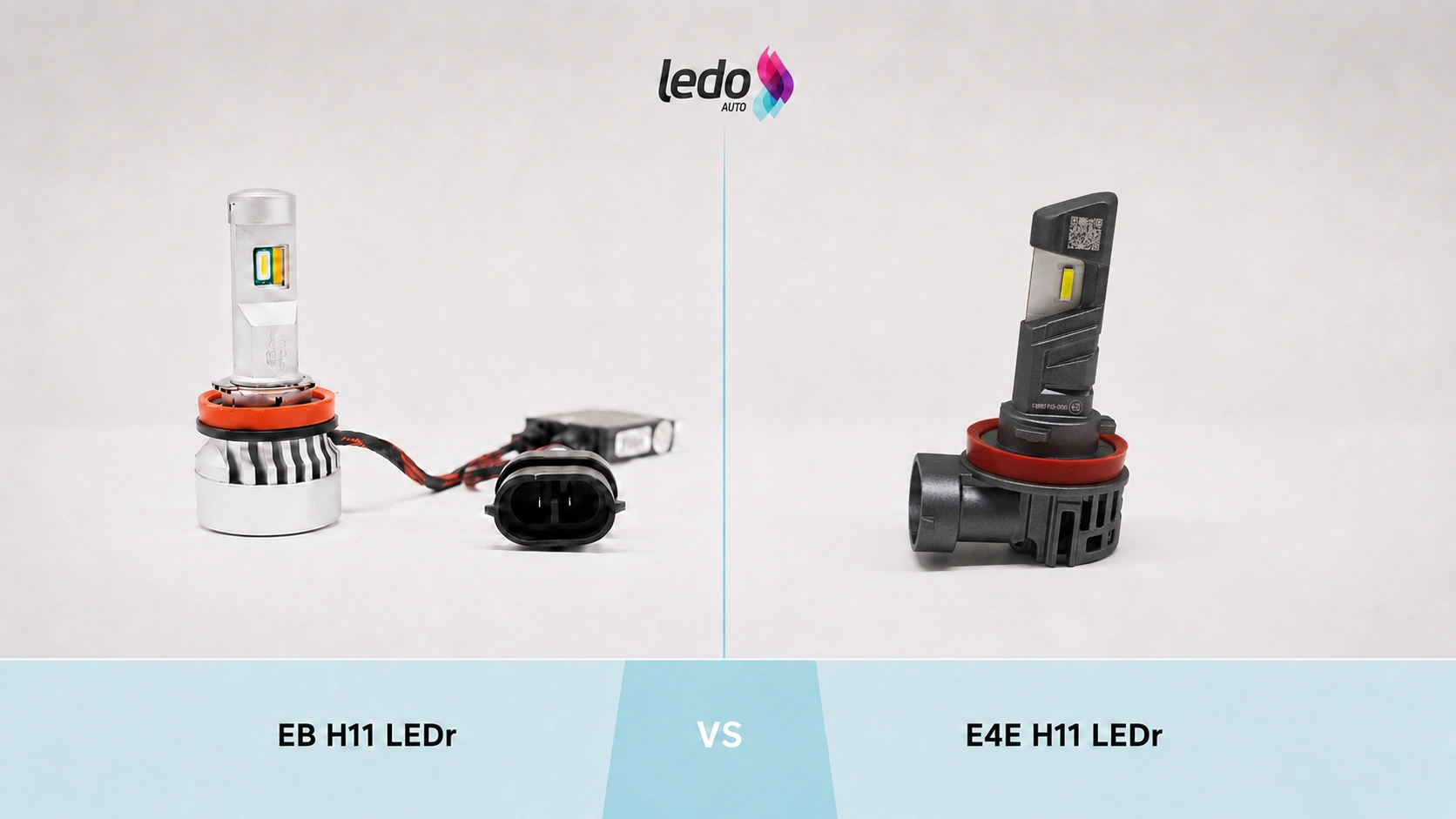
EB vs E4E H11 LEDr: A Side-by-Side Comparison
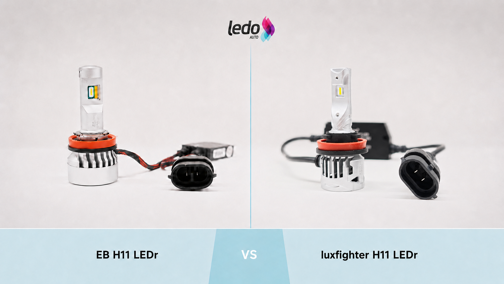
EB vs Luxfighter H11 LEDr: A Side-by-Side Comparison
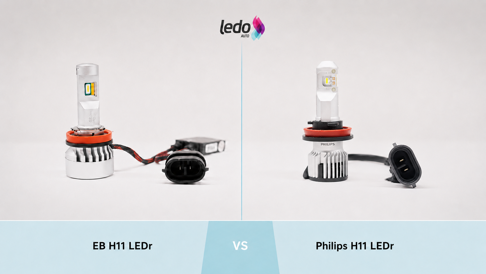
EB vs Philips H11 LEDr: A Side-by-Side Comparison
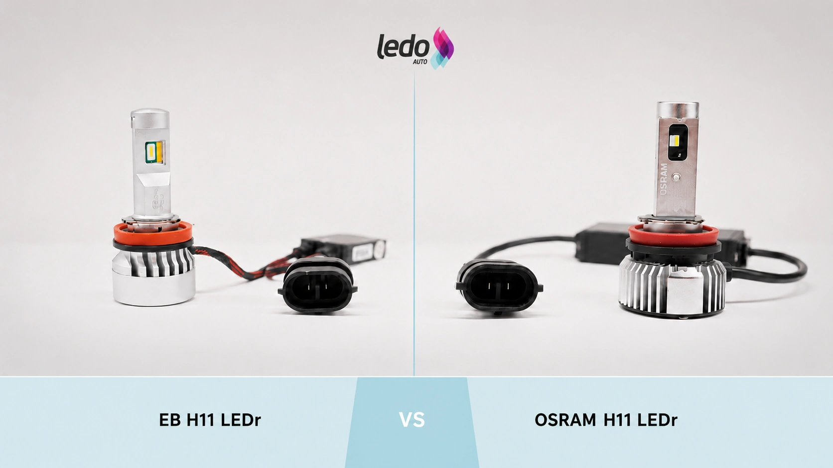
EB vs OSRAM H11 LEDr: A Side-by-Side Comparison
E4E H11 LEDr Review: Construction, Beam Pattern, Illuminance, Temperature and Noise
luxfighter H11 LEDr Review: Construction, Beam Pattern, Illuminance, Temperature and Noise
OSRAM H11 LEDr Review:Construction, Beam Pattern, Illuminance, Temperature and Noise
Philips H11 LEDr Review:Construction, Beam Pattern, Illuminance, Temperature and Noise