These two H11 LEDr samples share a similar connector interface, but the photographs reveal clearer differences when the emitters and beam patterns are viewed in sequence. This H11 LED bulb comparison follows what the camera and instruments recorded: PGJ19-2 construction, emitting geometry, projected distribution, surface temperature and fan noise. EB uses a thinner opposing-surface structure, produces stronger right-side illuminance, and records lower temperature and fan noise; Philips records the lower B50L value and higher readings at 25L and 25V. The Philips package was damaged during transport, so unavailable packaging measurements are left blank rather than estimated.
Compared samples: one EB H11 LEDr lamp and one Philips H11 LEDr lamp. Every photograph and measurement below belongs to these two samples. The individual records are available in the EB H11 LEDr review and Philips H11 LEDr review.
Test conditions
Both lamps operated at 13.2 V in a 26°C test environment. Illuminance was recorded after a 30-minute warm-up at the same E-Mark panel points from 3.5 m. Emitting-area surface temperature was recorded after 30 minutes, and operating noise was measured 3.5 cm from the fan.
Key Comparison Points
- Packaging: EB records 118 × 55 × 120 mm, 0.779 L and 51 g. The Philips packaging fields remain blank because its packaging was damaged in transit.
- Lamp construction: both samples use an H11 connector, PGJ19-2 locating structure and metal retaining spring. Their heat sinks, cables and external-driver housings differ.
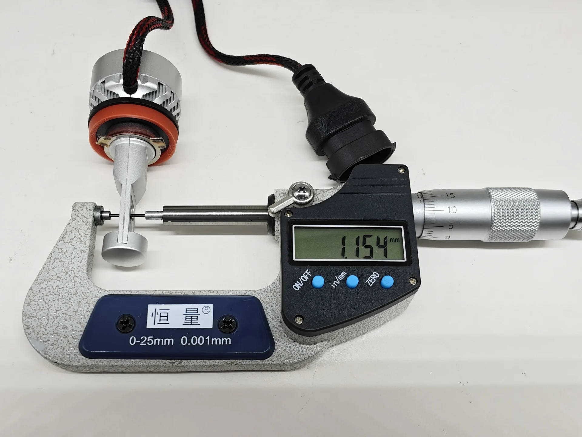
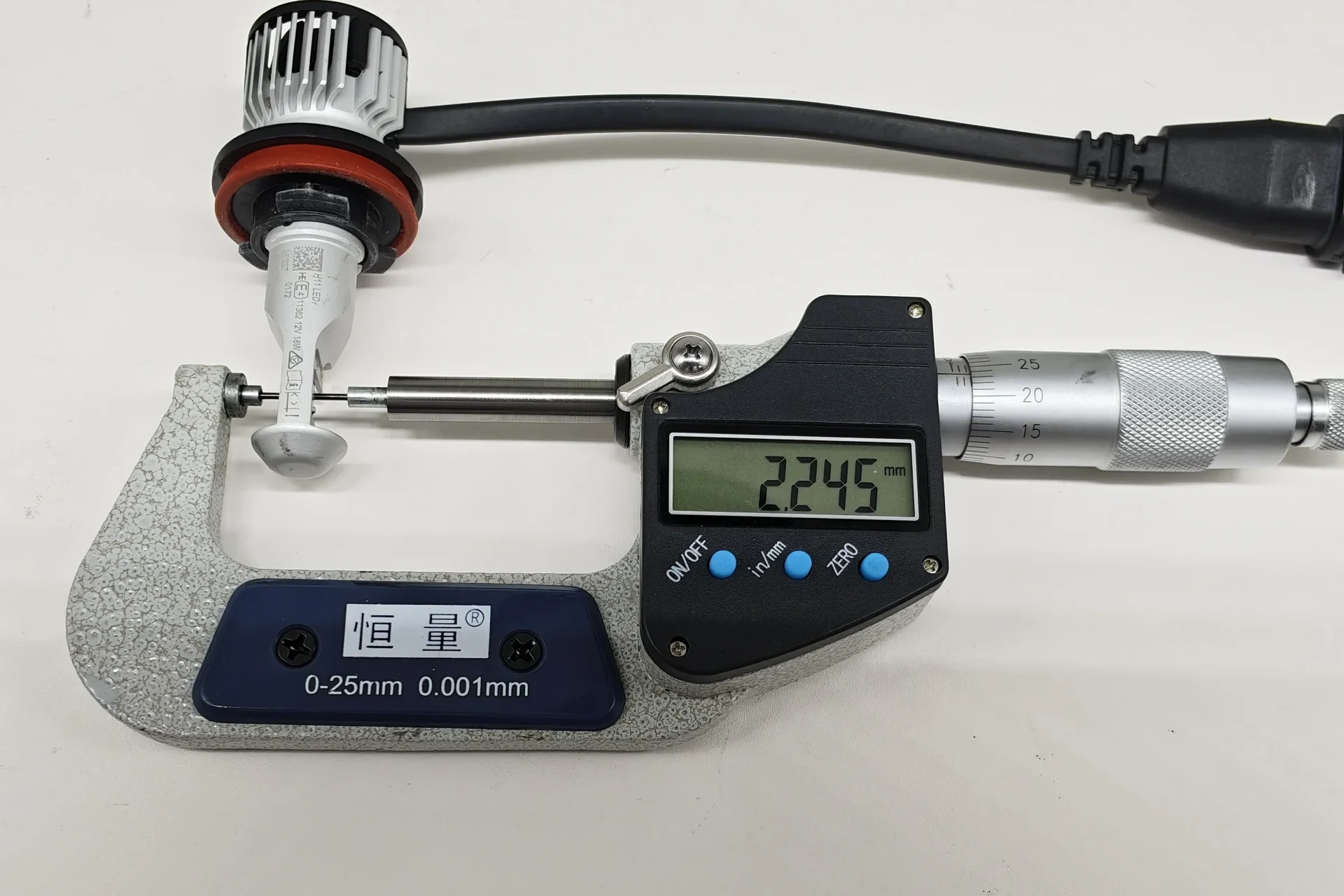
- Emitting geometry: EB measures 1.154 mm between opposing LED emitting surfaces; Philips measures 2.245 mm.
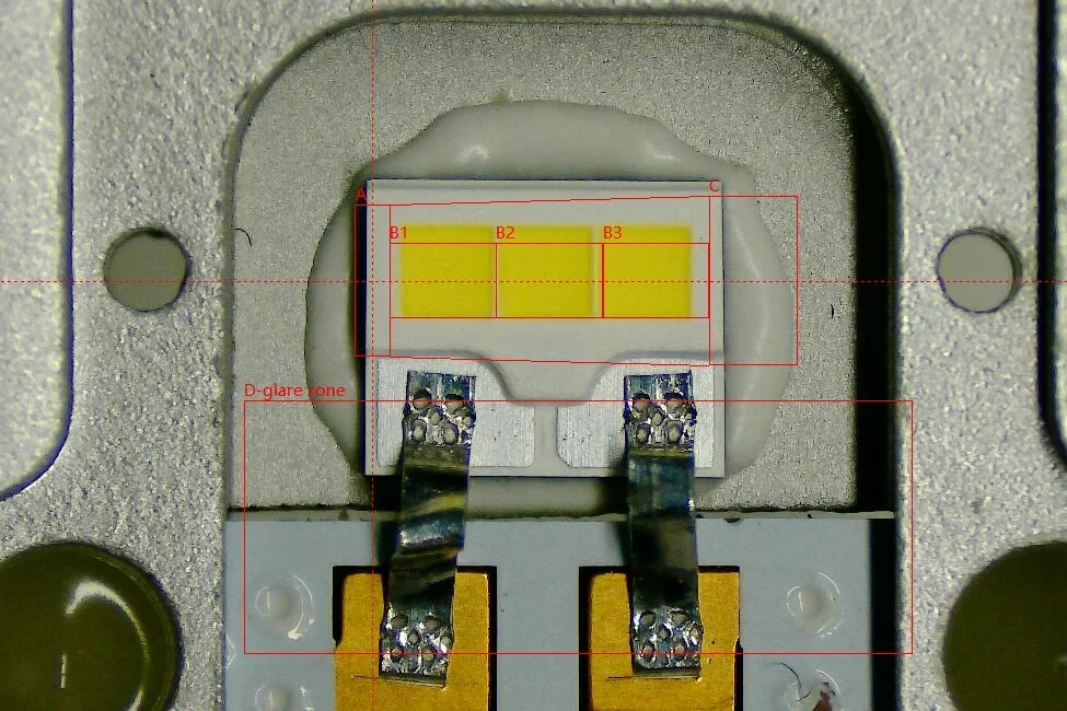
- Box system: both illuminated records cover B1–B3. The EB D-glare zone remains dark, while several small bright marks are visible in the Philips D zone.
- Beam and illuminance: EB is higher at 25R, 50R, 75R and EMAX. Philips records the lower B50L value, with a difference of 1.5 lux.
- Temperature and noise: EB is 16.5°C lower after 30 minutes and 2.1 dBA lower at the 3.5 cm noise measurement distance.
Packaging Section
Due to damage to the Philips packaging during shipping, we were unable to provide a complete view of the packaging. The product itself and the test results were not affected. Once we receive the replacement packaging materials for the Philips H11 LEDr, we will update and re-upload the comparison.
1.Package and included contents
| Differentiating item | EB | Philips | Recorded result |
|---|---|---|---|
| Package dimensions | 118 × 55 × 120 mm | / | Waiting for an update… |
| Nominal external volume | 0.779 L | / | Waiting for an update… |
| Empty-package mass | 51 g | / | Waiting for an update… |
| Package presentation | Main hardware with two plain inner boxes | / | Waiting for an update… |
Philips packaging was damaged in transit. The blank cells are intentional; no dimensions, volume, weight or kit contents were estimated.
EB supplies a complete set of packaging measurements for storage, carton and packaging-weight calculations. The unavailable Philips record prevents a direct package-size or weight comparison.
Lamp Construction Comparison
The construction comparison separates the shared H11 mounting features from the different cooling, cable and driver layouts. Both samples use a keyed connector, PGJ19-2 locating structure, red sealing ring and metal retaining spring.
1.Lamp and driver overview
The front views compare the heat-sink, cable and external-driver designs.
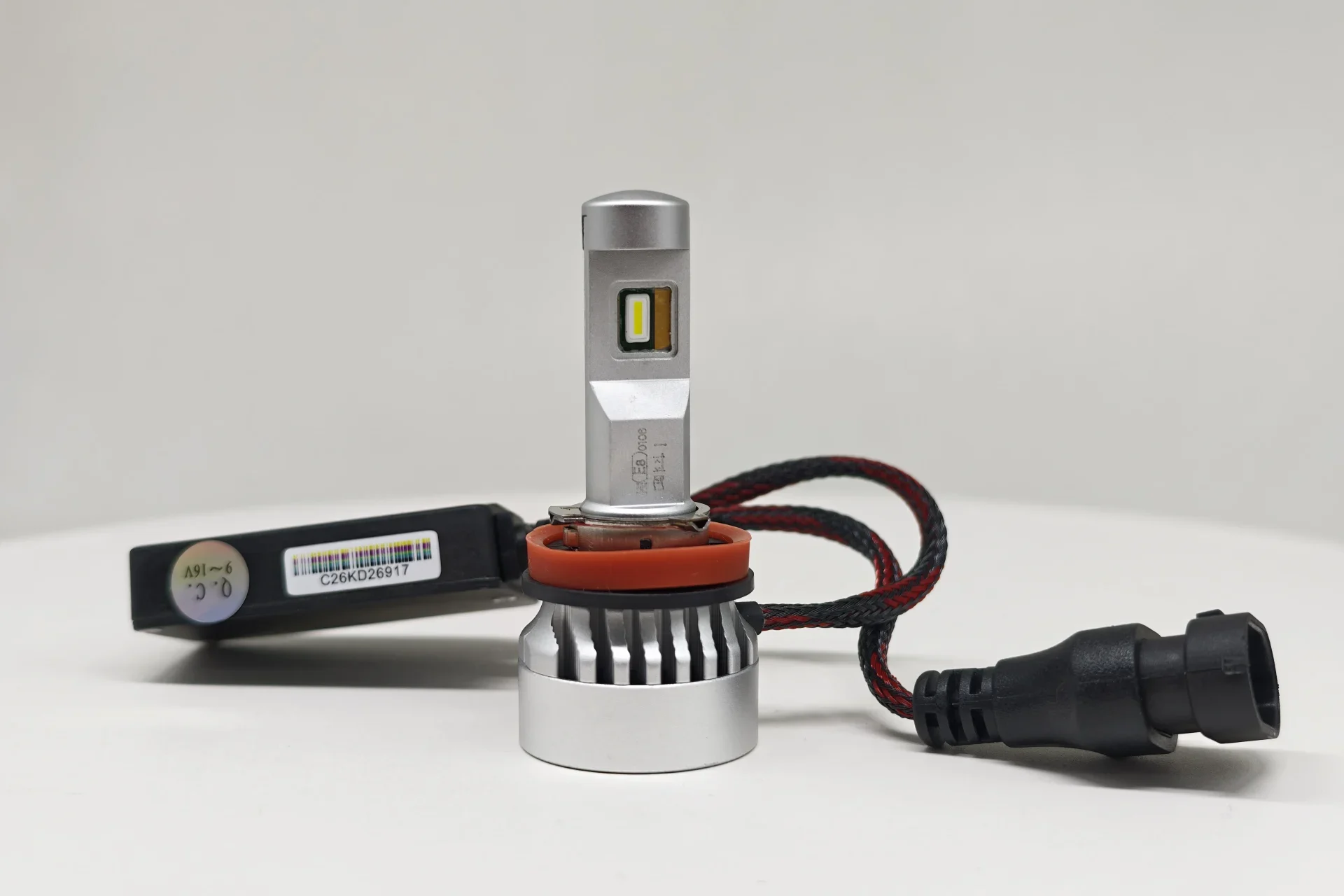
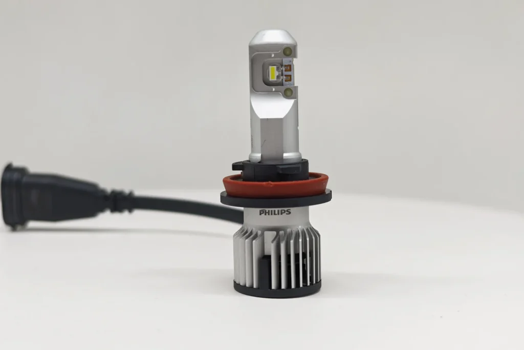
Both samples use fan-assisted cooling. EB combines a cylindrical rear heat sink, braided cable and a separate narrow driver housing. Philips uses a radial-finned rear heat sink and smooth cable; no separate driver housing is visible in the supplied front-view record.
2.H11 Connector Interface
The images show the connector face used by each sample.
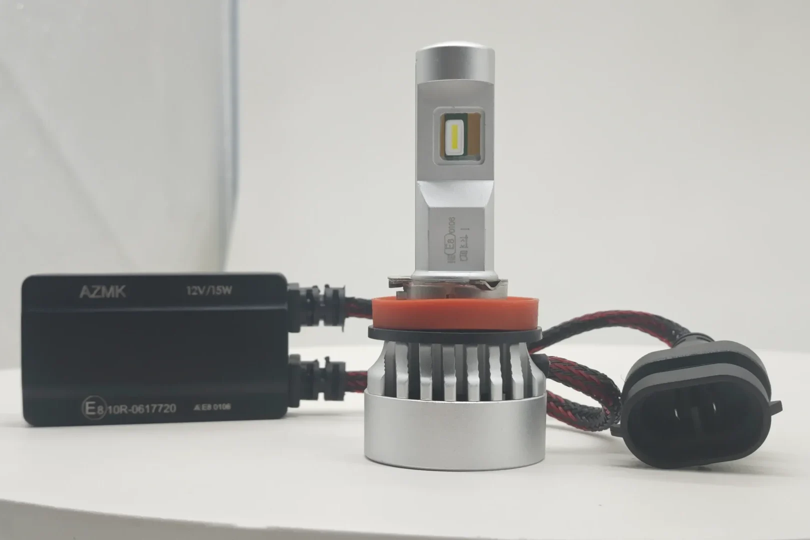
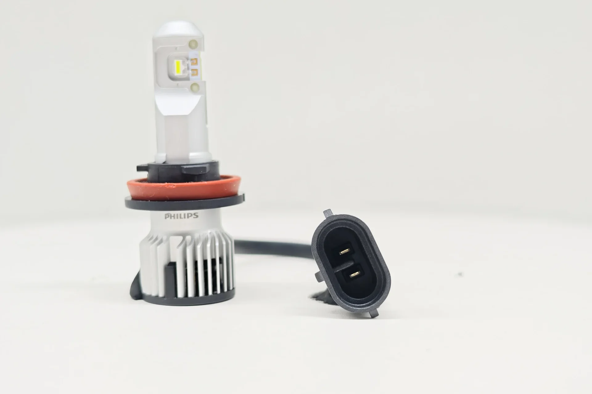
Both samples use a keyed, oval two-pin H11 connector with a central divider.
3.PGJ19-2 base and locating features
The top views show the PGJ19-2 mounting structure of each sample.
| H11 Base Standard Reference |
|---|
| Reference | What it specifies | Structural effect | Purpose |
|---|---|---|---|
| UN R37 and the H11 LEDr category sheet | H11 LEDr uses the H11 PGJ19-2 cap designation. | Defines the applicable H11 mounting interface. | Keeps the replacement source within the H11 category configuration. |
| IEC 60061-1, sheet 7004-110-3 | Defines the PGJ19 cap dimensions and locating features relevant to interchangeability, including the three-tab interface. | Controls the installation direction and the cap’s reference position in the holder. | Allows the cap to mate with the corresponding PGJ19 holder. |
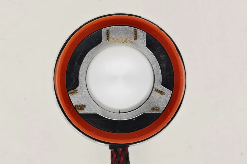
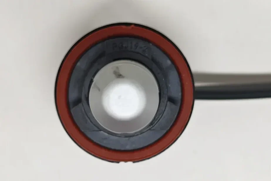
Both samples use the same keyed PGJ19-2 mounting structure, with asymmetric metal locating tabs and a red sealing ring.
4.Base installation-section measurement
| Why Measure Pillar Thickness | Main Impact | Relevance to Actual Headlight Performance |
|---|---|---|
| Light obstruction | The pillar can block part of the light emitted sideways or at oblique angles from the LED | An excessively thick pillar may block certain emission angles, resulting in incomplete angular light distribution or local dark areas |
| Heat transfer | The pillar is also part of the main thermal path from the LED chip to the heat sink | Its cross-section, material and internal structure affect how efficiently heat is transferred, influencing junction temperature and sustained light output |
| Structural strength and stability | The pillar provides mechanical support for the LED chip, PCB or substrate | An excessively thin pillar may reduce rigidity and increase the risk of displacement or deformation during assembly, vibration or thermal cycling |
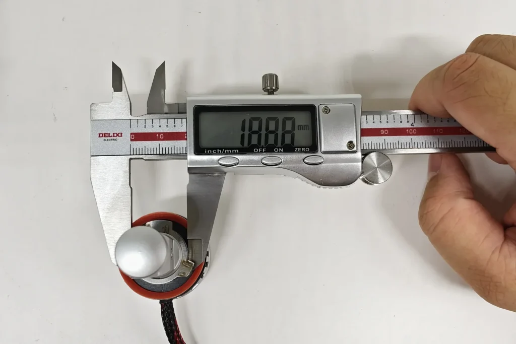
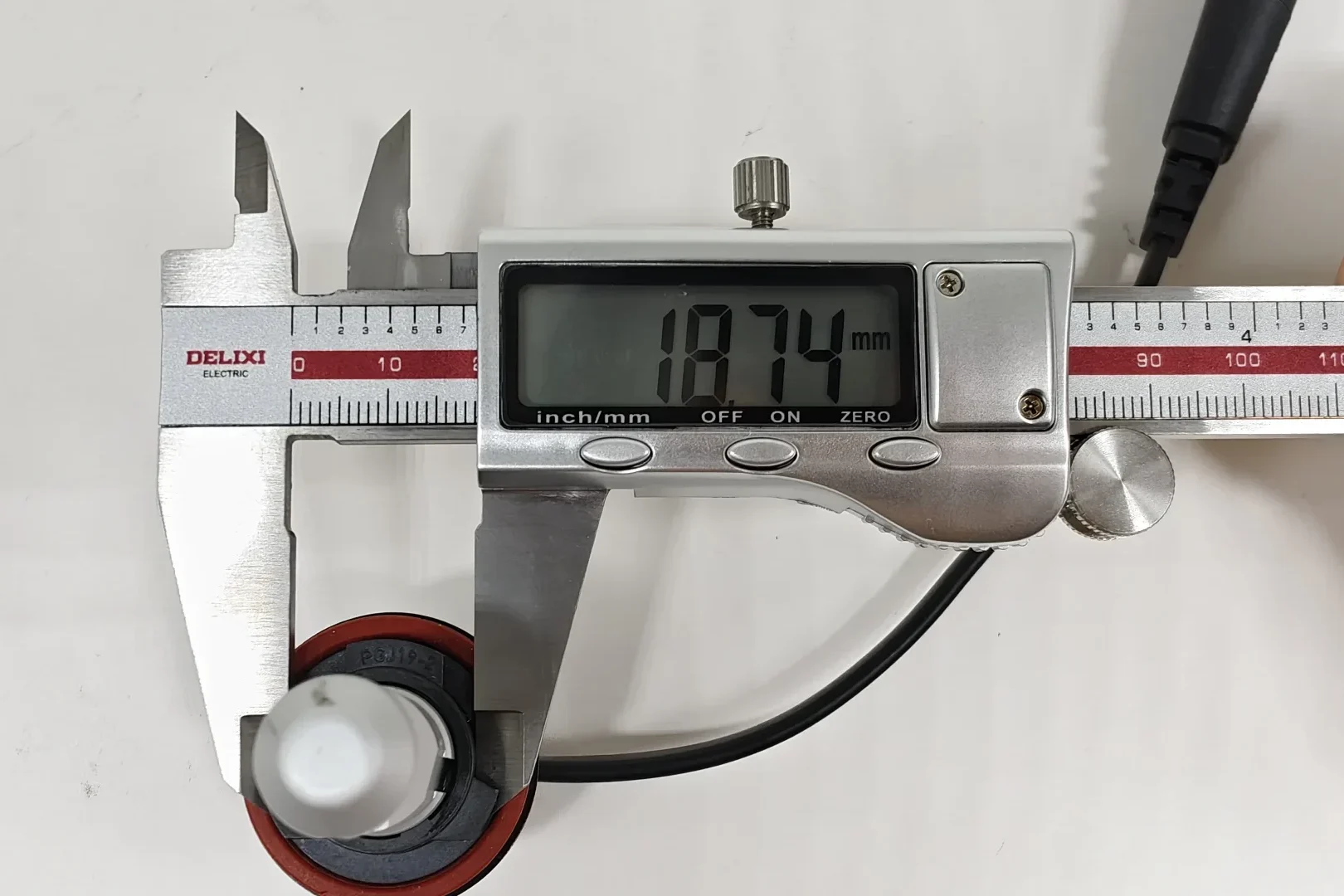
EB measures 18.88 mm, while Philips measures 18.74 mm at the installation section, a difference of only 0.14 mm, or about 0.75%.The two products are very close in this installation-section dimension. EB is slightly larger, but the difference is small.
5.Metal retaining spring
This metal retaining spring stabilises the lamp’s axial and rotational position, helping maintain the LED emitting surfaces in the intended optical reference position.
| Retaining-Spring Standard Reference |
|---|
| Reference | What it specifies | Structural effect | Purpose |
|---|---|---|---|
| IEC 60061-2, PGJ19 holder and connector sheet 7005-110-3 | Defines the corresponding PGJ19 holder and connector interface, including the retaining arrangement used with the cap. | Affects whether the cap remains seated in its installed position. | Helps retain the light source after the keyed base has located it. |
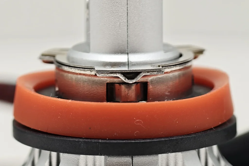
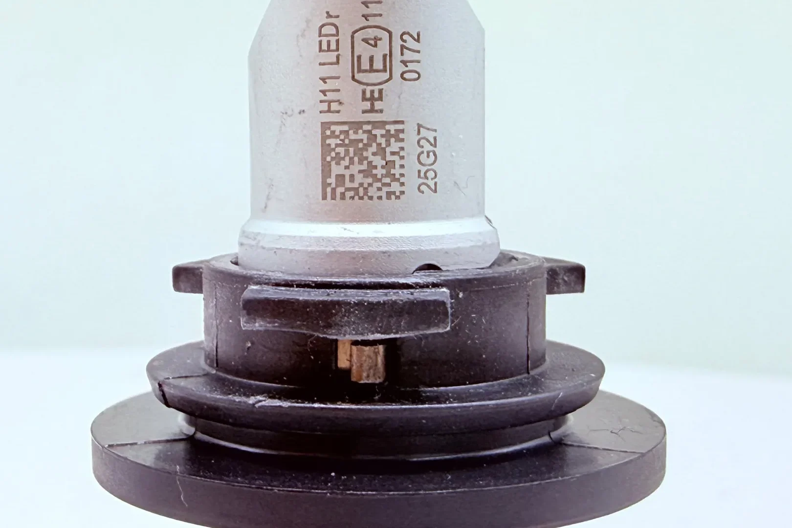
Both samples include a separate metal retaining spring beneath the flange.
| Lamp-Construction Comparison |
|---|
| Item | EB | Philips | Practical difference |
|---|---|---|---|
| Installation-section diameter | 18.88 mm | 18.74 mm | EB is 0.14 mm larger at the measured section. |
| Locating structure | Keyed PGJ19-2 base with metal locating tabs | Keyed PGJ19-2 base with metal locating tabs | Both use the same visible locating principle to establish installation direction and reference position. |
| Sealing structure | Red sealing ring | Red sealing ring | Both use the same visible sealing arrangement. |
| Metal retaining spring | Present | Present | Both use a separate spring to keep the lamp seated after the keyed base establishes its position. |
| Rear cooling assembly | Cylindrical heat sink and fan | Radial-finned heat sink and fan | The different profiles require different shapes of rear installation space. |
| Cable | Braided outer covering | Smooth outer covering | EB adds a braided protective layer, while Philips uses a simpler smooth cable. |
| External driver | Separate narrow driver housing | No separate driver housing visible in the supplied record | EB uses a clearly separated power-control layout; Philips has fewer visible external components. |
Both samples use the same visible PGJ19-2 locating, sealing and spring-retention arrangement, with only a 0.14 mm difference in installation-section diameter. EB stands out with its braided cable and separate narrow driver, providing a protected and clearly organised modular layout. Philips uses a radial-finned heat sink and shows no separate driver housing, giving it a simpler rear assembly with fewer external components to arrange. EB offers the more structured and robust-looking construction, while Philips provides the cleaner component layout.
LED Emitting Structure and Box System
This section compares the visible emitting-area geometry, the distance between opposing LED emitting surfaces and the position of the illuminated areas within the Box-system reference frame. The category definitions and limits follow the official UNECE UN Regulation No. 37 materials.
1.LED emitting-surface close-up
The close-ups compare the shape and arrangement of the visible LED emitting areas.
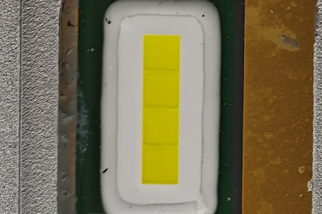
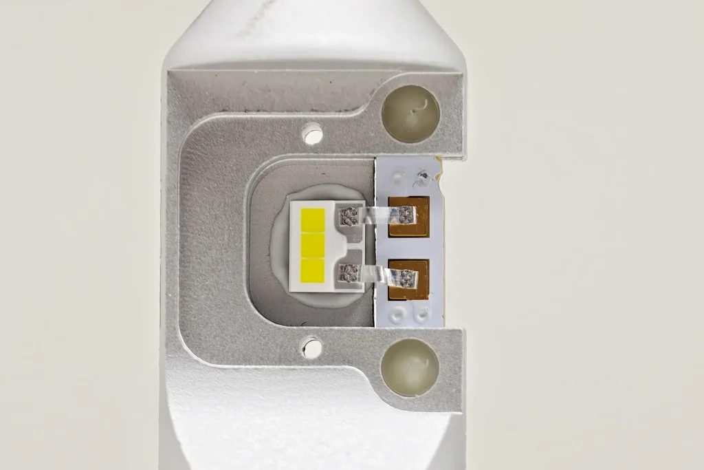
EB presents one continuous rectangular phosphor window. Philips presents three separate rectangular phosphor segments. This is a visible geometry difference; the optical result is assessed from the beam and illuminance records.
2.Distance between opposing LED emitting surfaces
For LED emitting surfaces, the UNECE Official specification defines this distance as parameter z and requires it to be no more than 2.9 mm.The distance between the two opposing LED emitting surfaces affects how compact the light source is. A thinner emitting structure can help the LED better match the focal geometry of a headlamp originally designed for a filament bulb, which may improve beam control.
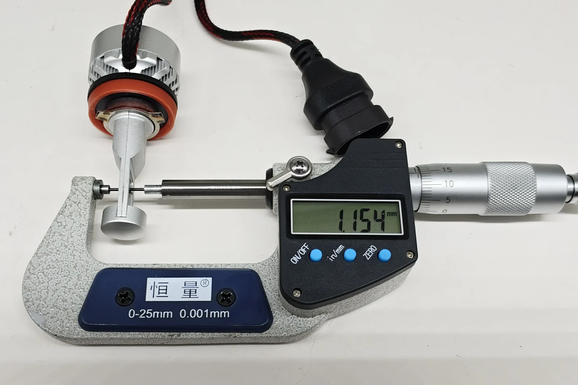
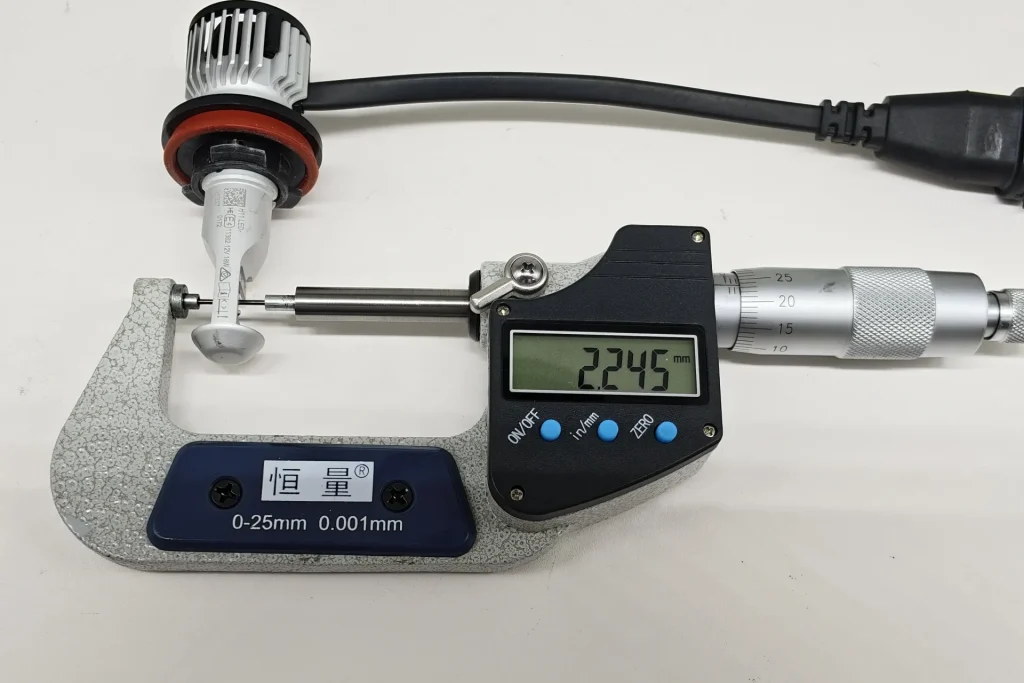
EB measures 1.154 mm and Philips 2.245 mm between the opposing LED emitting surfaces. EB is 1.091 mm thinner, or 48.60% lower than Philips. Both measured values are below the 2.9 mm Configuration-2 category limit.
3.Box system reference-frame check
The Box system separates the effective emitting region into Areas A, B and C, with B1–B3 showing how the core region is distributed. Area D records unwanted emission outside the intended emitting region.
| H11 LEDr Box-System Reference Criteria |
|---|
| Area | UNECE requirement | What the area represents | Why it matters |
|---|---|---|---|
| A+B+C | ≥ 90% of total luminous flux E | Main effective emitting region | Shows whether most emitted light remains inside the defined region. |
| Area A | ≤ 10% of A+B+C | One side of the core emitting region | Limits excessive flux on one side of Area B. |
| Area B | ≥ 72% of A+B+C | Core emitting region | Requires most effective flux to remain in the central region. |
| B1, B2, B3 | Each ≥ 15% of Area B | Three subdivisions of Area B | Checks that the core output is distributed across all three sections. |
| Area C | ≤ 22% of A+B+C | Opposite side of the core emitting region | Limits excessive flux beyond the other side of Area B. |
| Area D | Required contrast between A+B+C and D | Region outside the main emitting area | Controls unwanted emission outside the intended region. |
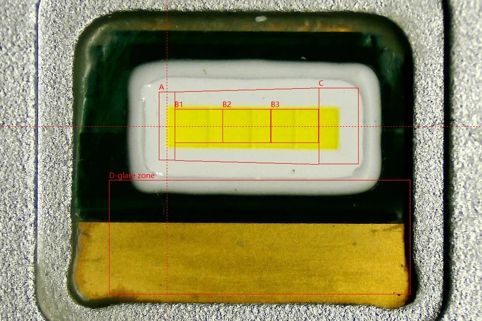
EB uses one continuous phosphor strip across B1–B3, while Philips divides the same core region among three separate phosphor segments. EB also extends farther into Area C. This structural difference matters because a continuous emitting surface avoids the two physical gaps visible between the Philips segments and provides a more uninterrupted source for the headlamp optics.
4.Box system with the emitting area illuminated
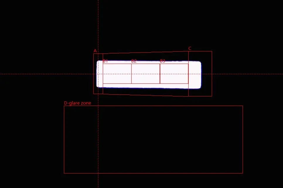
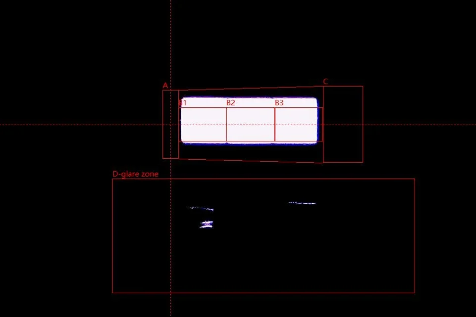
Reference-frame observation: both unlit records place the visible emitting structures within the upper A–C framework. EB shows one continuous rectangular window; Philips shows three separate emitting segments in the same comparison area.
EB forms a continuous illuminated band across B1, B2 and B3, with broad vertical overlap through the B region. Philips also illuminates all three subdivisions, but its band sits higher within the reference frame. Area D remains dark in the EB image, while several isolated bright marks are visible in the Philips D region.
| Box-System Reference-Frame Comparison |
|---|
| Area | Reference focus | EB observation | Philips observation |
|---|---|---|---|
| A+B+C | Overall emitting-area envelope | The continuous phosphor strip lies mainly across Area B and extends into Area C. | Three separate phosphor segments lie mainly across Area B, with the final segment ending near the B/C boundary. |
| Area A | Emitting material before Area B | The phosphor strip begins close to the A/B boundary, with little visible overlap into A. | The first phosphor segment also begins close to the A/B boundary, with little visible overlap into A. |
| Area B | Core emitting region | One continuous phosphor strip occupies the core region. | Three individual phosphor segments occupy the core region, with two visible gaps between them. |
| B1 / B2 / B3 | Coverage across the three subdivisions | The continuous phosphor surface spans B1, B2 and B3 without interruption. | Each subdivision contains a separate phosphor segment. |
| Area C | Emitting material beyond Area B | The right end of the phosphor strip extends visibly into C. | The rightmost segment approaches the B/C boundary, with less extension into C. |
| Area D | Material outside the main emitting region | No phosphor surface extends into D. | No phosphor surface extends into D; the visible metal terminals belong to the supporting structure rather than the emitting area. |
| Opposing-Surface Distance |
|---|
| Item | EB | Philips | Difference |
|---|---|---|---|
| Distance between opposing emitting surfaces | 1.154 mm | 2.245 mm | EB is 1.091 mm smaller (48.60%). |
EB combines a continuous phosphor strip across B1–B3 with a 48.60% smaller distance between the opposing emitting surfaces. Philips covers the same three subdivisions with separate phosphor segments, leaving two physical gaps, and uses a thicker dual-sided emitting structure. For buyers, EB provides a thinner, uninterrupted emitting geometry that more closely resembles a compact filament source and gives the headlamp optics a more concentrated source area to control.
Beam Pattern and Illuminance Comparison
The white-wall images show the overall low-beam shape, the rainbow maps show hotspot concentration, and the nine-point table identifies the measured distribution differences.
1.White-wall beam pattern
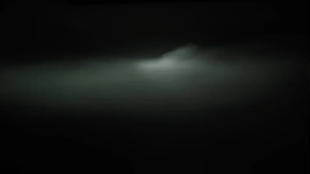
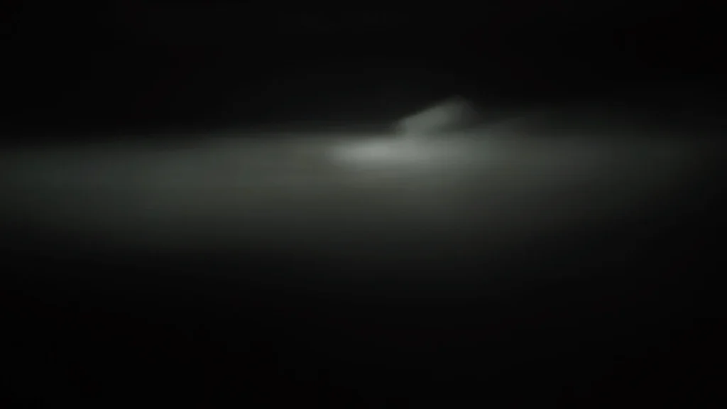
Both products form a recognizable low-beam pattern, but EB keeps more light below the cutoff, while Philips shows more upward spread and haze around the rising section.
This matches the earlier structural findings. EB has a smaller opposing emitting-surface distance (1.154 mm vs 2.245 mm) and better alignment across B1–B3, giving the headlamp optics a more compact and accurately positioned light source. Philips’ higher emitting position changes the light entering the optical system, while the stray-light spots in Area D add unwanted emission outside the main emitting region. Together, these differences help explain the greater upward spread visible in the Philips beam pattern.
Overall Comparison
EB shows cleaner control above the cutoff, while Philips produces more upward light spread. The difference is consistent with their emitting thickness, B-area position and stray-emission characteristics.
2.Rainbow map and hotspot distribution
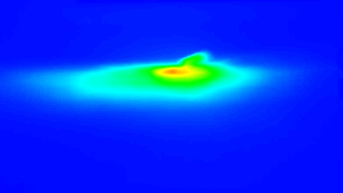
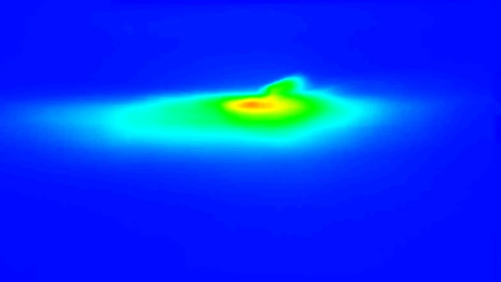
The rainbow maps show a different energy-distribution pattern between the two products. EB forms a broader, more continuous high-illuminance core, with the surrounding green and cyan zones spreading smoothly around the hotspot. Philips produces a narrower, more elongated hotspot, with the high-energy region extending further toward the right.
This difference is consistent with the earlier structural results. EB’s more compact emitting geometry and more complete alignment across B1–B3 give the headlamp optics a more stable source position, helping concentrate the projected energy around the intended hotspot. Philips’ higher emitting position changes how the light is distributed through the optical system, resulting in a more directional and elongated hotspot.
Overall Comparison
EB shows a fuller and more evenly distributed hotspot, while Philips concentrates the high-energy region into a narrower, more right-shifted shape. This indicates that the differences in emitting geometry are reflected not only in beam control, but also in how the useful light energy is distributed within the main illumination zone.
3.Nine-point illuminance with B50L focus
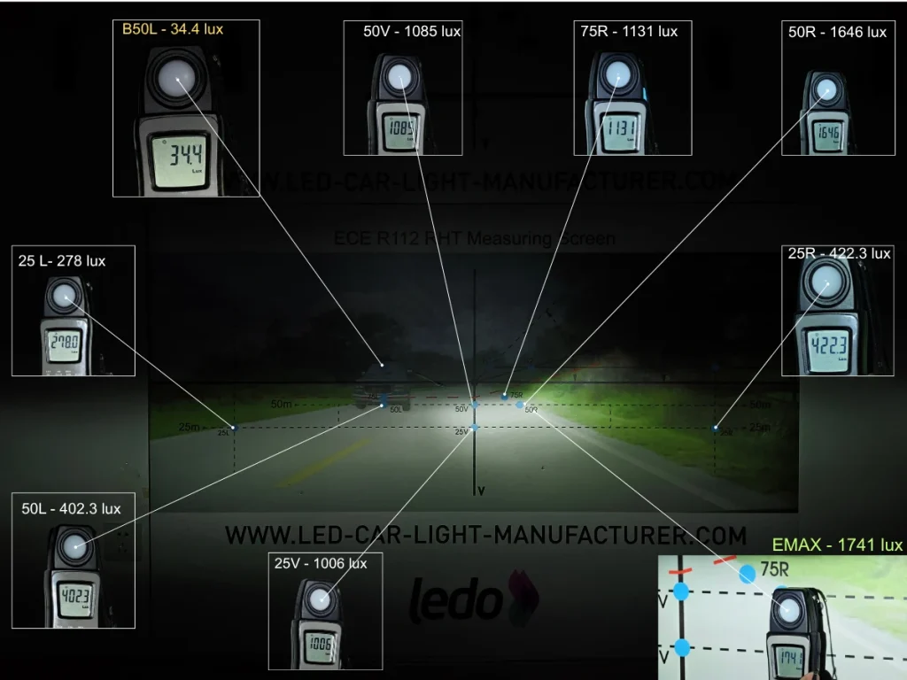
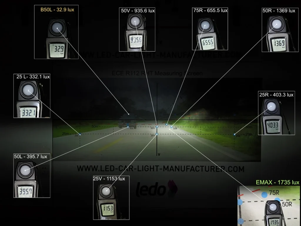
EB and Philips produce nearly identical peak illuminance, at 1,741 lux and 1,735 lux respectively, but distribute the available light differently. EB records higher illuminance at 50V and all three right-side points, including a 72.54% advantage at 75R and 20.23% at 50R, indicating stronger centre-right and longer-range roadside coverage. Philips is higher at 25L and 25V and records the lower B50L value of 32.9 lux, while the two lamps remain close at 50L.
| Beam-Pattern and Rainbow-Map Observations |
|---|
| Feature | EB | Philips | Key difference |
|---|---|---|---|
| Cutoff pattern | Clear horizontal cutoff and right-hand rise. | Similar cutoff structure and right-hand rise. | Both reproduce the basic low-beam pattern. |
| Light distribution | Stronger centre-right field with broader right-side coverage. | More light toward the outer-left and near-centre field. | The visual difference corresponds with EB’s higher 50V and right-side readings and Philips’ higher 25L and 25V readings. |
| Rainbow map | Compact hotspot below the rise with a broader green–cyan field extending rightward. | Similarly positioned hotspot with less surrounding high-intensity area on the right. | Peak intensity is nearly equal; the main difference is how the light is distributed around the hotspot. |
| Illuminance Comparison |
|---|
| Point | What it represents | EB (lux) | Philips (lux) | Result |
|---|---|---|---|---|
| B50L | Glare-control point | 34.4 | 32.9 | Philips is lower by 1.5 lux. |
| 25L | Outer-left field | 278 | 332.1 | Philips is 16.29% higher relative to EB’s value. |
| 50L | Middle-left field | 402.3 | 395.7 | Readings are close; EB is 1.67% higher. |
| 50V | Central field | 1,085 | 935.6 | EB is 15.97% higher. |
| 25V | Near-centre field | 1,006 | 1,153 | Philips is up 14.61% compared to EB. |
| 75R | Far-right field | 1,131 | 655.5 | EB is 72.54% higher. |
| 50R | Middle-right field | 1,646 | 1,369 | EB is 20.23% higher. |
| 25R | Near-right field | 422.3 | 403.3 | EB is 4.71% higher. |
| EMAX | Peak illuminance | 1,741 | 1,735 | Nearly identical; EB is 0.35% higher. |
EB and Philips reach almost the same peak illuminance, but EB distributes more light through the centre-right and right-side field. Its largest gains appear at 75R and 50R, while Philips is higher at 25L and 25V and records the lower B50L value. For buyers prioritising stronger right-side and longer-range road coverage, EB provides the more useful distribution.
| Beam Pattern and Illuminance Comparison Summary |
|---|
| Comparison | EB observation | Philips observation | Result |
|---|---|---|---|
| White-wall beam pattern | More light remains below the cutoff, leaving the area above it cleaner. | More haze and upward spread appear around the rising cutoff section. | EB provides better control of light above the cutoff. |
| Rainbow map and hotspot | A broader, more continuous high-illuminance core transitions smoothly into the surrounding green and cyan zones. | A narrower, more elongated high-illuminance region extends farther toward the right. | EB produces a fuller and more evenly distributed hotspot; Philips produces a more directional concentration. |
| Nine-point illuminance | Higher at 50V, 25R, 50R, 75R and EMAX. | Higher at 25L and 25V, with a 1.5 lux lower B50L reading. | EB provides stronger centre-right and right-side output, including advantages of 72.54% at 75R and 20.23% at 50R. Peak output is nearly identical. |
EB and Philips reach almost the same peak illuminance, but EB controls and distributes the available light more effectively across the centre-right and right-side field. Its cleaner cutoff area, fuller hotspot and substantially higher 50R and 75R readings give EB the stronger overall beam result. Philips provides more light at 25L and 25V and records the lower B50L value, but buyers prioritizing controlled upward light, balanced hotspot coverage and stronger right-side illumination will find EB the more capable option.
Temperature and Fan Noise
Surface temperature was recorded after 30 minutes. Fan noise was measured separately at 3.5 cm.
1.Emitting-Area Surface Temperature After 30 Minutes
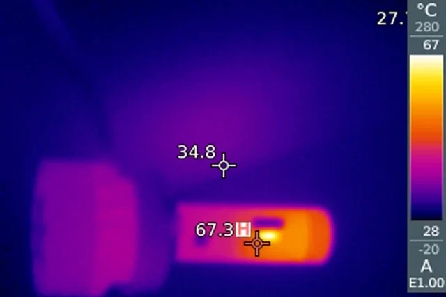
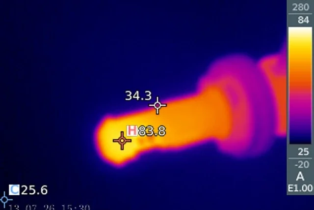
EB measures 67.3°C at the LED emitting section, while Philips measures 83.8°C. The surrounding areas are almost the same at about 34°C.
Philips is 16.5°C hotter at the measured emitting surface. EB shows lower local heat accumulation under the same test conditions.
These are surface temperatures, not LED junction temperatures.
2.Operating noise at 3.5 cm from the fan
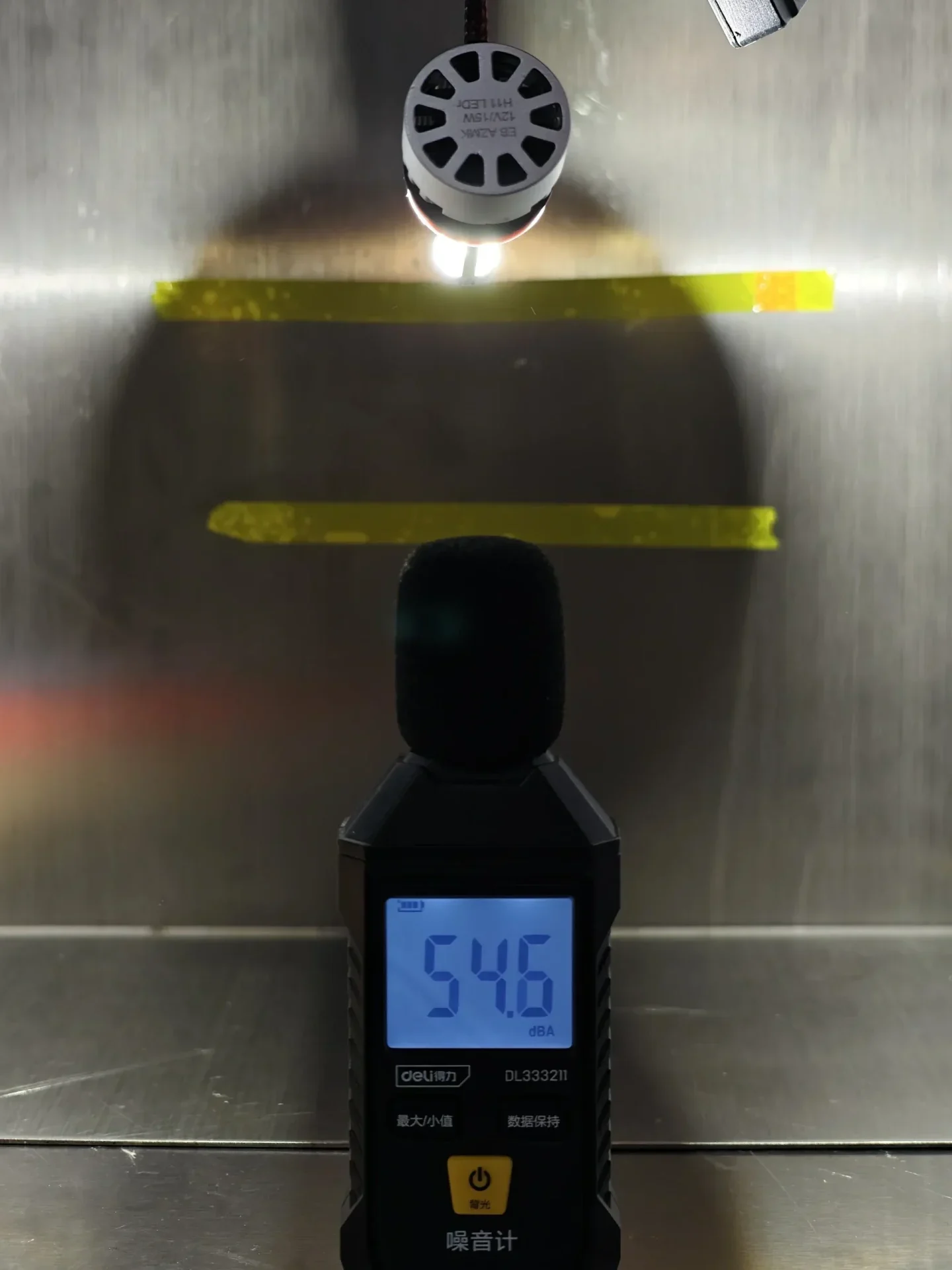
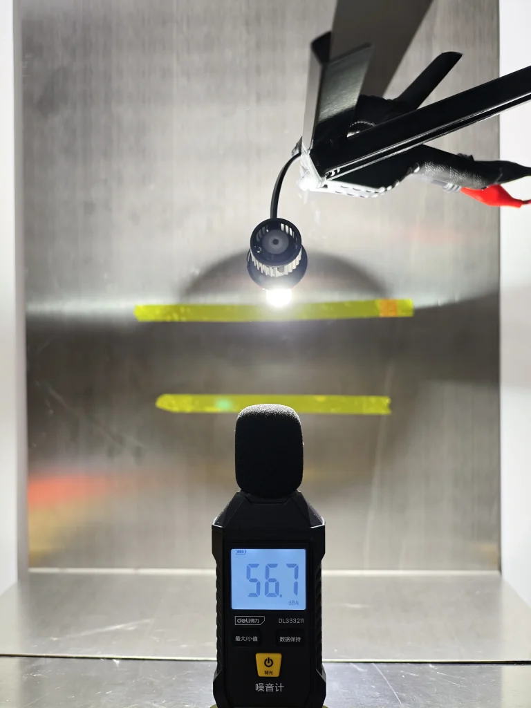
EB records 54.6 dBA and Philips 56.7 dBA at 3.5 cm from the fan. EB is 2.1 dBA lower in this close-range measurement.
| Temperature and Fan-Noise Results |
|---|
| Metric | Test condition | EB | Philips | Difference |
|---|---|---|---|---|
| Emitting-area surface temperature | 13.2 V, 26°C ambient, after 30 minutes | 67.3°C | 83.8°C | EB is 16.5°C lower. |
| Fan noise | Measured 3.5 cm from the cooling fan | 54.6 dBA | 56.7 dBA | EB is 2.1 dBA lower. |
Under the same recorded test conditions, EB operates with a 16.5°C lower emitting-area surface temperature after 30 minutes and produces 2.1 dBA less fan noise at 3.5 cm. EB receive lower measured operating heat together with quieter active cooling in this comparison.
What This Comparison Means for Customers
- Packaging: EB provides complete dimensions, volume and weight data, and its package includes a hanging feature for peg-display retail. Philips packaging could not be compared because it was damaged in transit.
- Construction: Both use a keyed PGJ19-2 base and metal retaining spring. EB has a braided cable and separate narrow driver; Philips presents fewer visible external components.
- Emitting geometry: EB’s 1.154 mm opposing-surface distance is 48.60% thinner than Philips’ 2.245 mm structure. EB also covers B1–B3 more fully and keeps Area D visually dark.
- Light distribution: EB produces a cleaner cutoff area, a fuller hotspot and stronger centre-right output. It is 72.54% higher at 75R and 20.23% higher at 50R, while EMAX is nearly identical.
- Temperature and noise: EB records a 16.5°C lower emitting-area temperature after 30 minutes and 2.1 dBA less fan noise at 3.5 cm.
EB delivers the stronger combination of compact emitting geometry, controlled beam distribution, right-side illumination, lower operating temperature and quieter cooling. Philips records the lower B50L value and higher readings at 25L and 25V, but EB performs better across more of the practical comparison areas. For customers prioritizing beam control, thermal performance and balanced road illumination, EB is the more complete option.
EB vs Philips H11 LEDr FAQ
Author: Jack Liu, Co-founder and Director of Product at LEDOAUTO
Reviewed by: LEDOAUTO Engineering Team; verified in accordance with official documents from the United Nations Economic Commission for Europe (UNECE)
Last Updated: September 3, 2026
The category terminology used in this comparison follows the UNECE light-source category resolutions. Additional context is available in the ECE R37 H11 LEDr background.
References
Philips H11 LEDr Review:Construction, Beam Pattern, Illuminance, Temperature and Noise