These two H11 LEDr samples differ clearly in packaging, mounting structure and optical performance. E4E uses a smaller, lighter package but has no hanging feature, while its tested lamp uses a universal base without a separate metal retaining spring; EB includes both a hanging feature and separate spring retention. EB also delivers thinner emitting geometry, higher right-side and peak illuminance, and lower surface temperature and fan noise, while E4E records the lower B50L value and higher readings at 25L and 25V.
Compared samples: one EB H11 LEDr lamp and one E4E H11 LEDr lamp. The photographs and measurements come from the EB H11 LEDr review and E4E H11 LEDr review.
Before Testing
Two mounting points should be checked first. UN R37 defines H11 LEDr as a category-specific light source using the H11 PGJ19-2 cap, so E4E’s multi-base design should be verified for the correct H11 configuration. Separately, the retaining spring affects installation stability; an unsuitable or missing spring can allow the bulb to move from its intended position. See the UNECE H11 LEDr specification and IEC 60061.
Test Conditions
Both lamps were tested at 13.2 V and 26°C. Illuminance was measured at the same E-mark reference points from 3.5 m after a 30-minute warm-up. Emitting-area surface temperature was recorded after 30 minutes, and fan noise was measured at 3.5 cm.
Key Comparison Points
- Packaging: dimensions, contents and empty-box weight.
- Construction: base, retaining spring, connector and driver layout.
- Emitting structure: emitting-area design, opposing-surface distance and Box System.
- Optical performance: beam pattern, rainbow map, B50L, EMAX and nine-point illuminance.
- Temperature and noise: 30-minute surface temperature and close-range fan noise.
Packaging Comparison
The packaging comparison covers shipping efficiency, included components and suitability for common retail-display formats.
1.Package and included contents
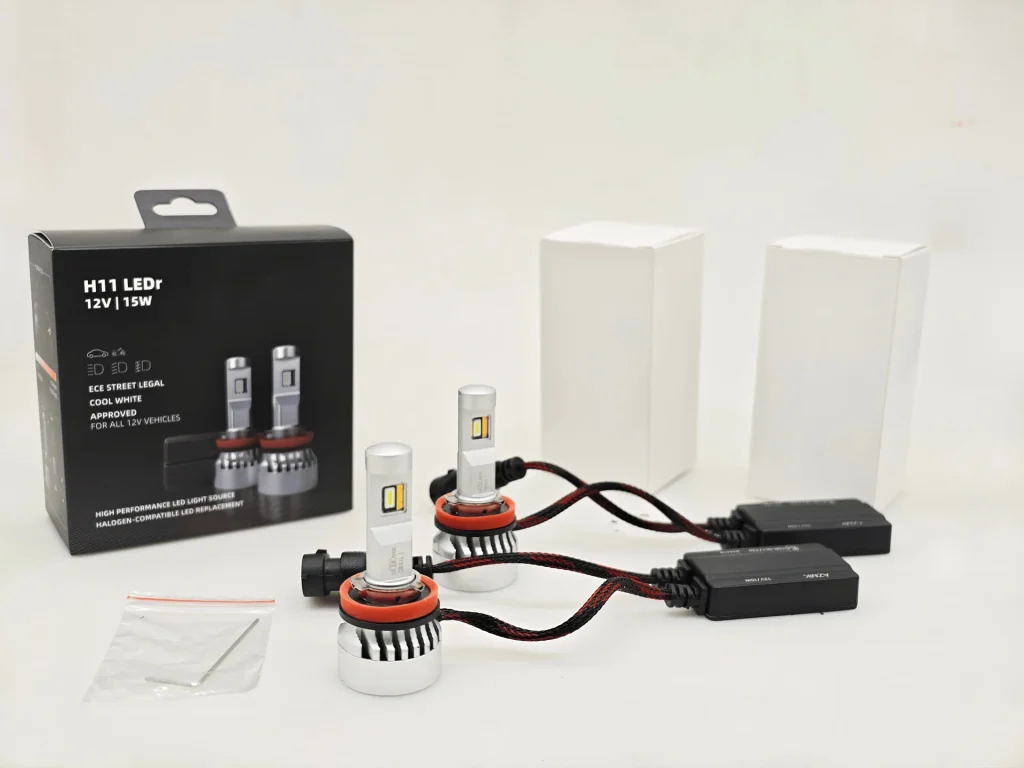
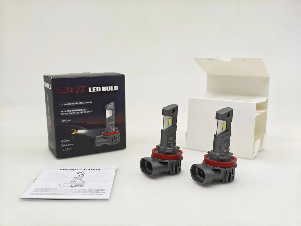
EB is shown with two lamps, two external drivers, two plain inner boxes and an accessory bag. E4E is shown with two one-piece lamps, a white inner box and a printed product manual. E4E needs less space because it has no separate driver boxes or driver leads, but its outer package has no hanging tab or Euro-slot for direct peg-hook display.
2.External package dimensions
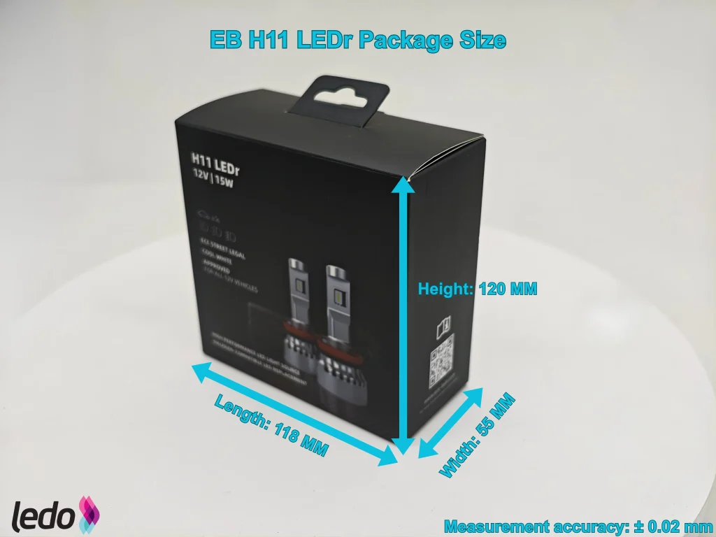
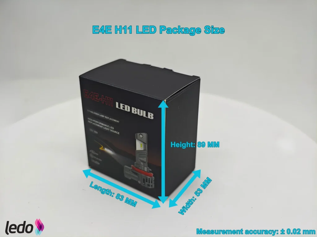
EB measures 118 × 55 × 120 mm, giving a nominal external volume of 0.779 L. E4E measures 83 × 53 × 89 mm, approximately 0.392 L. E4E uses 49.73% less box volume than EB.
3.Empty-package weight
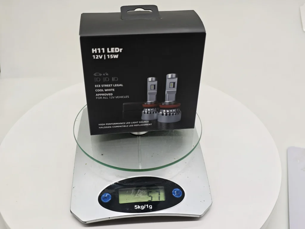
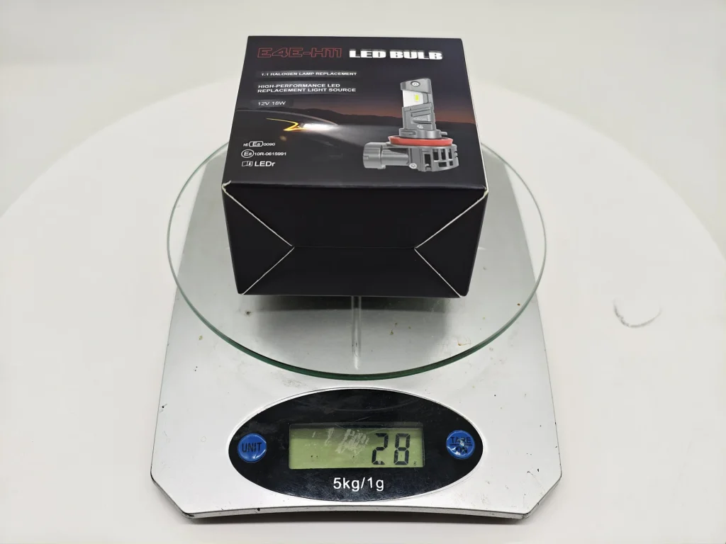
E4E’s empty package weighs 28 g, compared with 51 g for EB. E4E is 23 g lighter, or 45.10% lower in empty-package weight.
| Packaging Size, Weight and Contents |
|---|
| Item | EB | E4E | Difference |
|---|---|---|---|
| External dimensions | 118 × 55 × 120 mm | 83 × 53 × 89 mm | E4E is smaller in all three recorded dimensions. |
| Nominal external volume | 0.779 L | 0.392 L | E4E is 49.73% smaller. |
| Empty-package weight | 51 g | 28 g | E4E is 23 g lighter (45.10%). |
| Kit layout | Lamps, separate drivers and two inner boxes | One-piece lamps and a white inner box | E4E has fewer separate components to pack. |
| Hanging-display feature | It has packaging hooks, so it can be displayed directly on the shelves | No hanging tab or Euro-slot on the tested pack | E4E is less convenient for sales channels that rely on peg-hook displays. |
E4E’s package is smaller and lighter, which benefits bulk storage and transport. Its lack of a hanging tab, however, makes the tested pack less suitable for direct peg-hook display and may require a different outer pack for some retail channels. EB’s larger package accommodates the separate driver modules.
Lamp Construction Comparison
The construction comparison covers both the electronic layout and mounting design. EB uses external leads with a separate driver, while E4E integrates the connector into the rear housing and uses a multi-base design. The mounting base and retaining structure are reviewed separately to show how the two products differ in positioning and securing the bulb during installation.
1.Lamp and driver overview
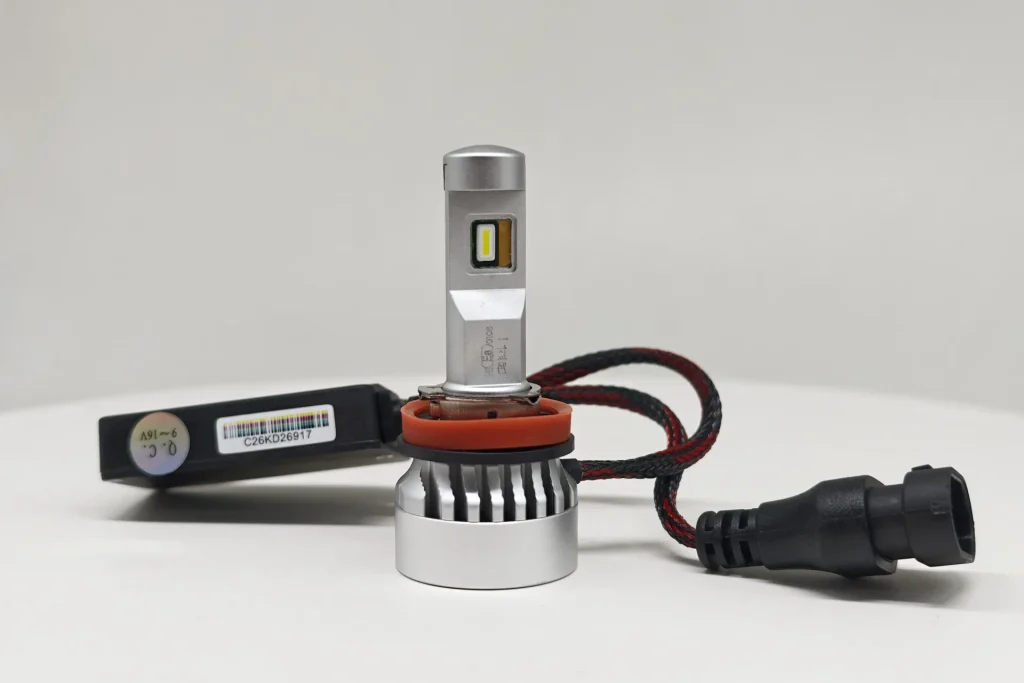
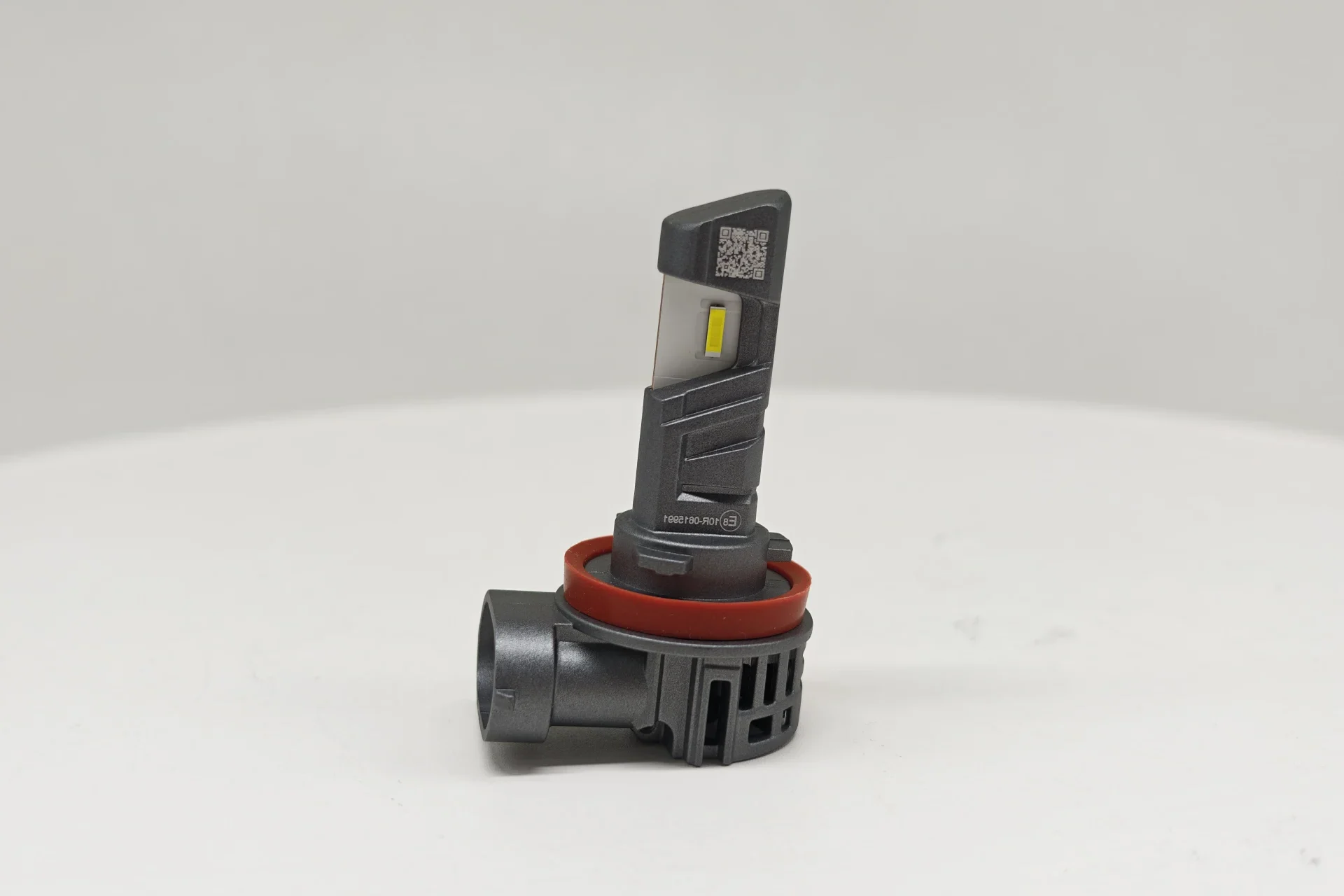
EB has a silver cylindrical rear heat sink, braided leads and a separate rectangular driver housing. E4E has a grey body with an open rear fan housing and a side-facing H11 connector built into that housing. No separate driver box or external driver lead is visible on E4E. Its integrated layout leaves fewer loose components to position behind the headlamp.
2.H11 Connector Interface
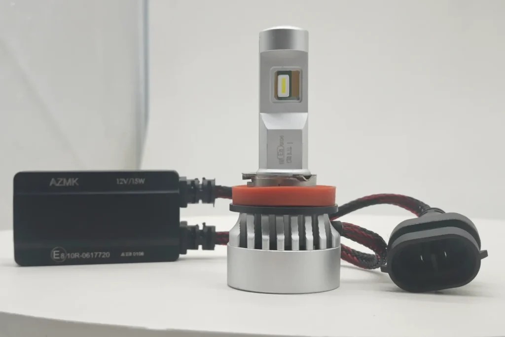
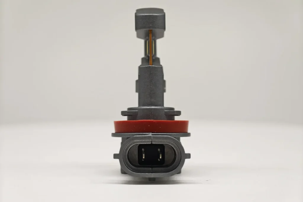
Both samples use a keyed, oval two-pin H11 connector. EB places the connector on a short lead, while E4E integrates it directly into the rear housing. This gives the two products a different installation layout: EB offers more flexibility in where the connector is positioned, while E4E keeps the connection more compact but closer to the lamp body.
3.PGJ19-2 base and locating features
UN Regulation No. 37 requires an LED replacement light source to use the same cap designation as its counterpart filament category. The H11 LEDr category specification identifies that cap as PGJ19-2 and refers its interface dimensions to IEC 60061 sheet 7004-110-3.
| Reference | What it specifies | Structural effect | Purpose |
|---|---|---|---|
| UN R37 and the H11 LEDr category sheet | H11 LEDr uses the H11 PGJ19-2 cap designation. | Defines the applicable H11 mounting interface. | Ensures that the replacement source follows the H11 category configuration. |
| IEC 60061-1, sheet 7004-110-3 | Defines the PGJ19 cap dimensions and locating features relevant to interchangeability, including the three-tab interface. | Controls installation direction and the cap’s reference position in the holder. | Allows the cap to mate with the corresponding PGJ19 holder. |
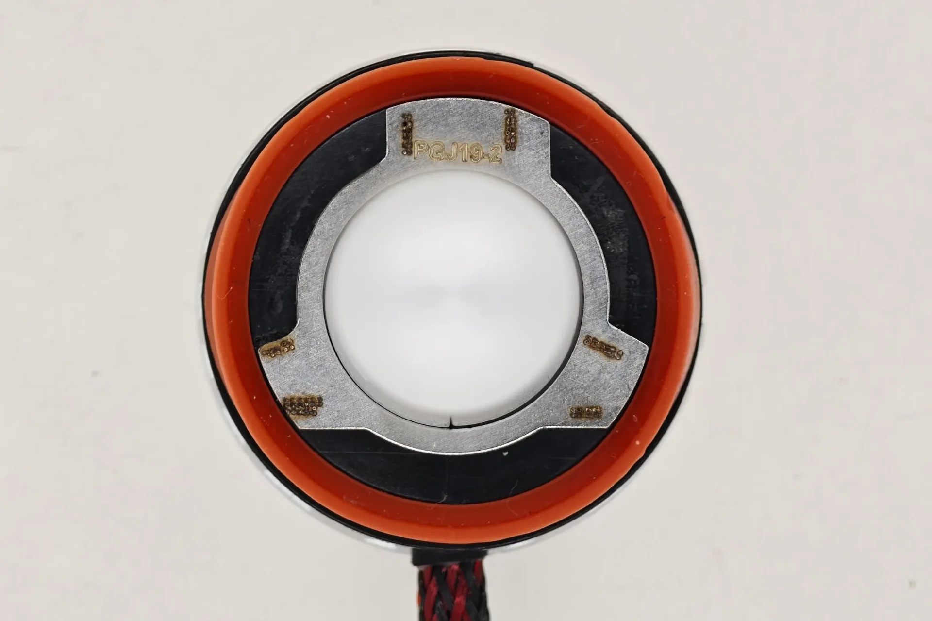
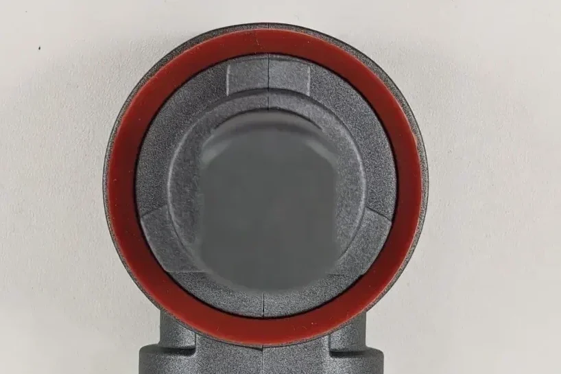
EB uses a dedicated H11 base with three metal locating tabs and a red sealing ring. The tested E4E sample uses a universal multi-base arrangement with three moulded locating tabs and a red sealing ring. The base design affects how each lamp is oriented and positioned during installation.
4.Base installation-section measurement
| Why Measure Pillar Thickness | Main Impact | Relevance to Actual Headlight Performance |
|---|---|---|
| Light obstruction | The pillar can block part of the light emitted sideways or at oblique angles from the LED | An excessively thick pillar may block certain emission angles, resulting in incomplete angular light distribution or local dark areas |
| Heat transfer | The pillar is also part of the main thermal path from the LED chip to the heat sink | Its cross-section, material and internal structure affect how efficiently heat is transferred, influencing junction temperature and sustained light output |
| Structural strength and stability | The pillar provides mechanical support for the LED chip, PCB or substrate | An excessively thin pillar may reduce rigidity and increase the risk of displacement or deformation during assembly, vibration or thermal cycling |
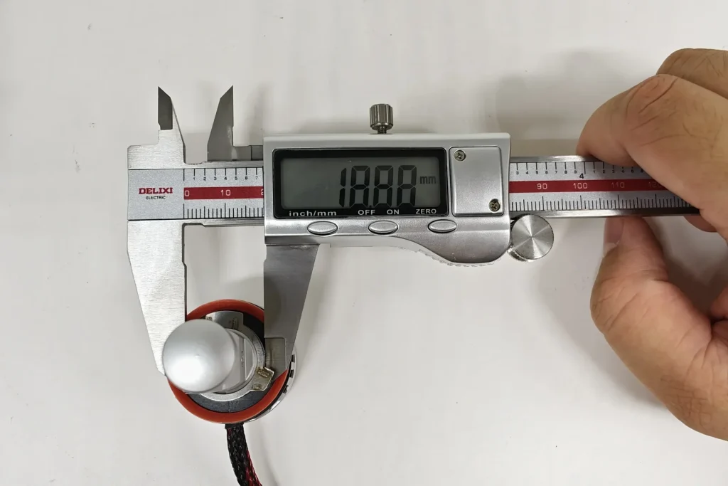
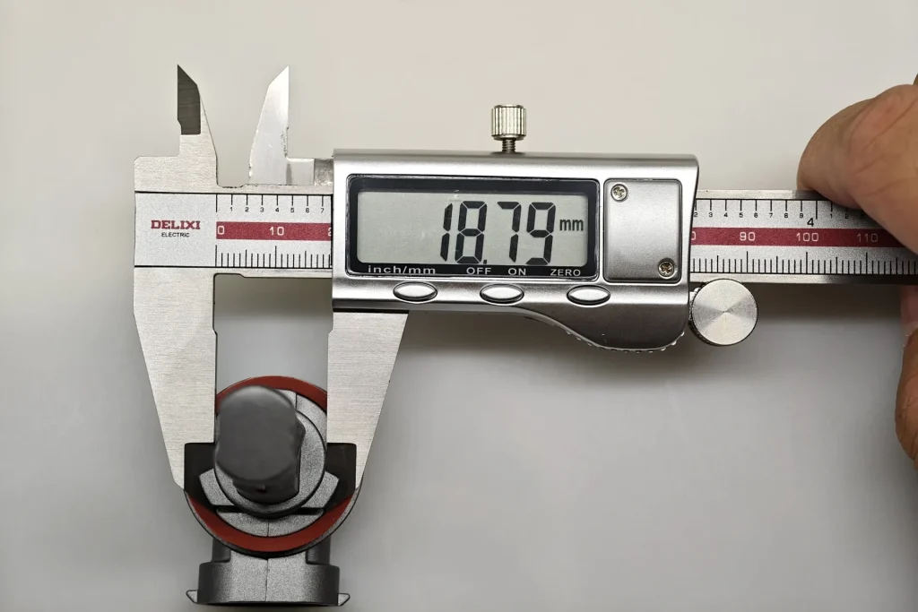
EB measures 18.88 mm and E4E 18.79 mm at the installation section. EB is 0.09 mm larger. This records the base dimension, separately from the emitting-surface spacing measured in the next section.
5.Metal retaining spring
A metal retaining spring provides elastic preload at the mounting interface. Its presence is a separate construction feature from the keyed shape and sealing ring.
| Reference | What it specifies | Structural effect | Purpose |
|---|---|---|---|
| IEC 60061-2, PGJ19 holder and connector sheet 7005-110-3 | Defines the corresponding PGJ19 holder and connector interface, including the retaining arrangement used with the cap. | Affects whether the cap remains seated in its installed position. | Helps retain the light source after it has been located by the three-tab base. |
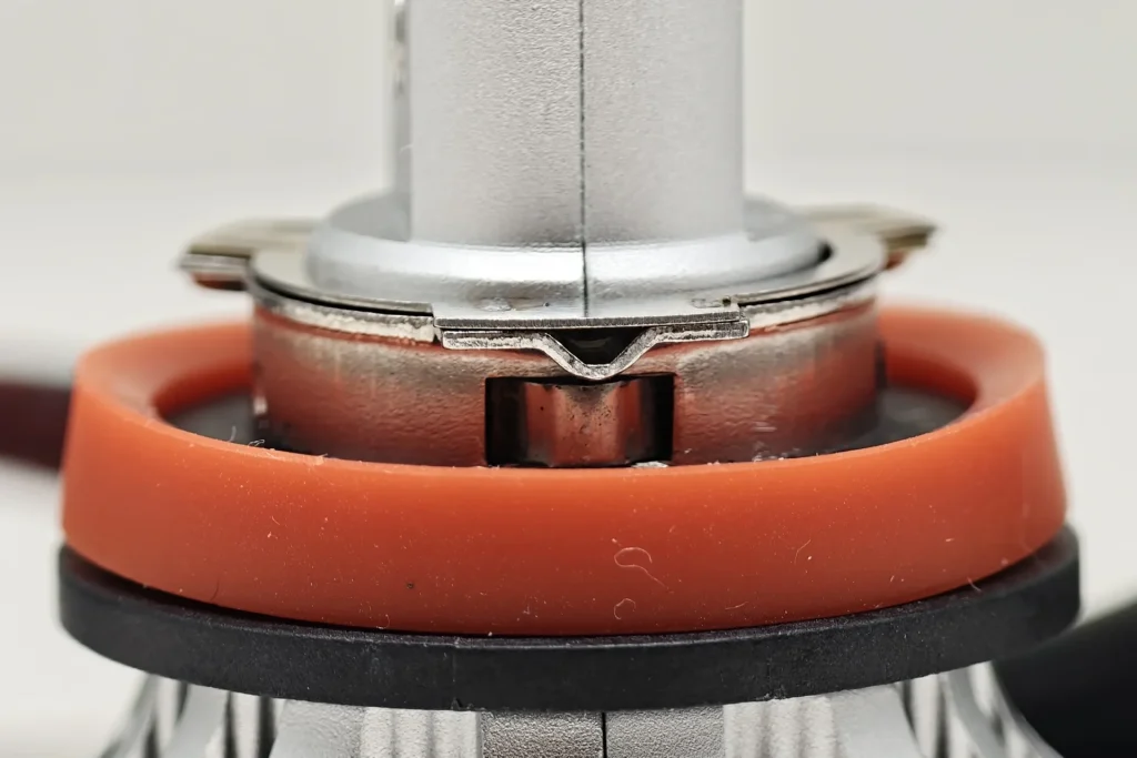
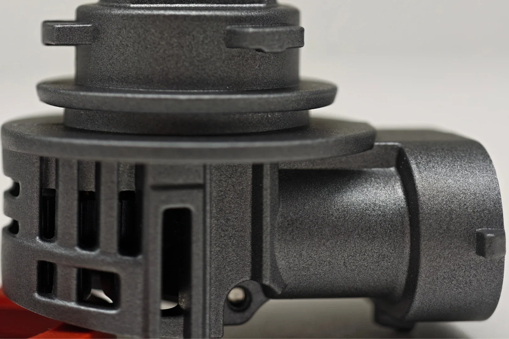
EB includes a separate metal retaining spring beneath the flange. The E4E base photographs show its locating collar and cooling housing without a separate metal retaining spring.
| Lamp-Construction Comparison |
|---|
| Item | EB | E4E | Practical difference |
|---|---|---|---|
| Base arrangement | Dedicated H11 base with three metal locating tabs | Universal multi-base arrangement with three moulded tabs | E4E’s exact supplied base requires configuration-specific fit and documentation checks. |
| Installation-section diameter | 18.88 mm | 18.79 mm | EB is 0.09 mm larger at the measured section. |
| Driver and wiring layout | Separate driver with external leads | Integrated assembly; no separate driver box shown | E4E has fewer loose components to route. |
| H11 connector position | At the end of a lead | Fixed to the rear housing | Different connector-access requirements. |
| Rear cooling assembly | Cylindrical heat sink and fan | Open fan housing with integrated connector | Different rear shape and space requirement. |
| Metal retaining spring | Separate metal spring present | No separate metal spring present | The samples use visibly different retaining structures. |
EB provides a dedicated H11 mounting structure with three locating tabs, a sealing ring and a separate metal retaining spring. E4E reduces wiring and external components through its integrated body, but uses a universal base and has no separate metal retaining spring.
LED Emitting Structure and Box System
The close-ups compare the emitting surfaces, the micrometer records their separation, and the Box images show source position. The category reference is the UNECE H11 LEDr Configuration-2 category-sheet amendment associated with UN Regulation No. 37.
1.LED emitting-surface close-up
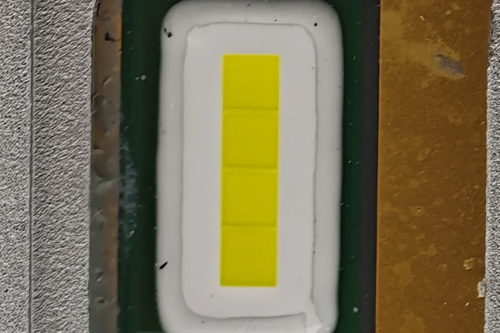
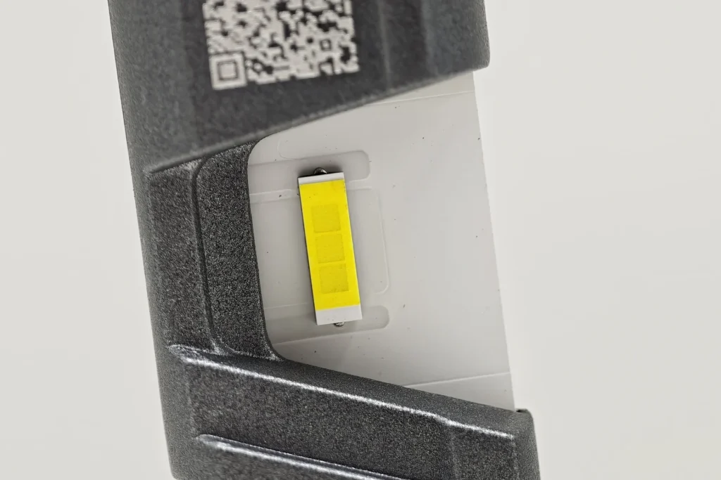
Both samples have a rectangular yellow phosphor window. EB shows four internal sections within a recessed package; E4E shows three internal areas along a narrow rectangular strip on a broad light-coloured substrate. These are visible construction differences, not a measured emitting-area comparison.
2.Distance between opposing LED emitting surfaces
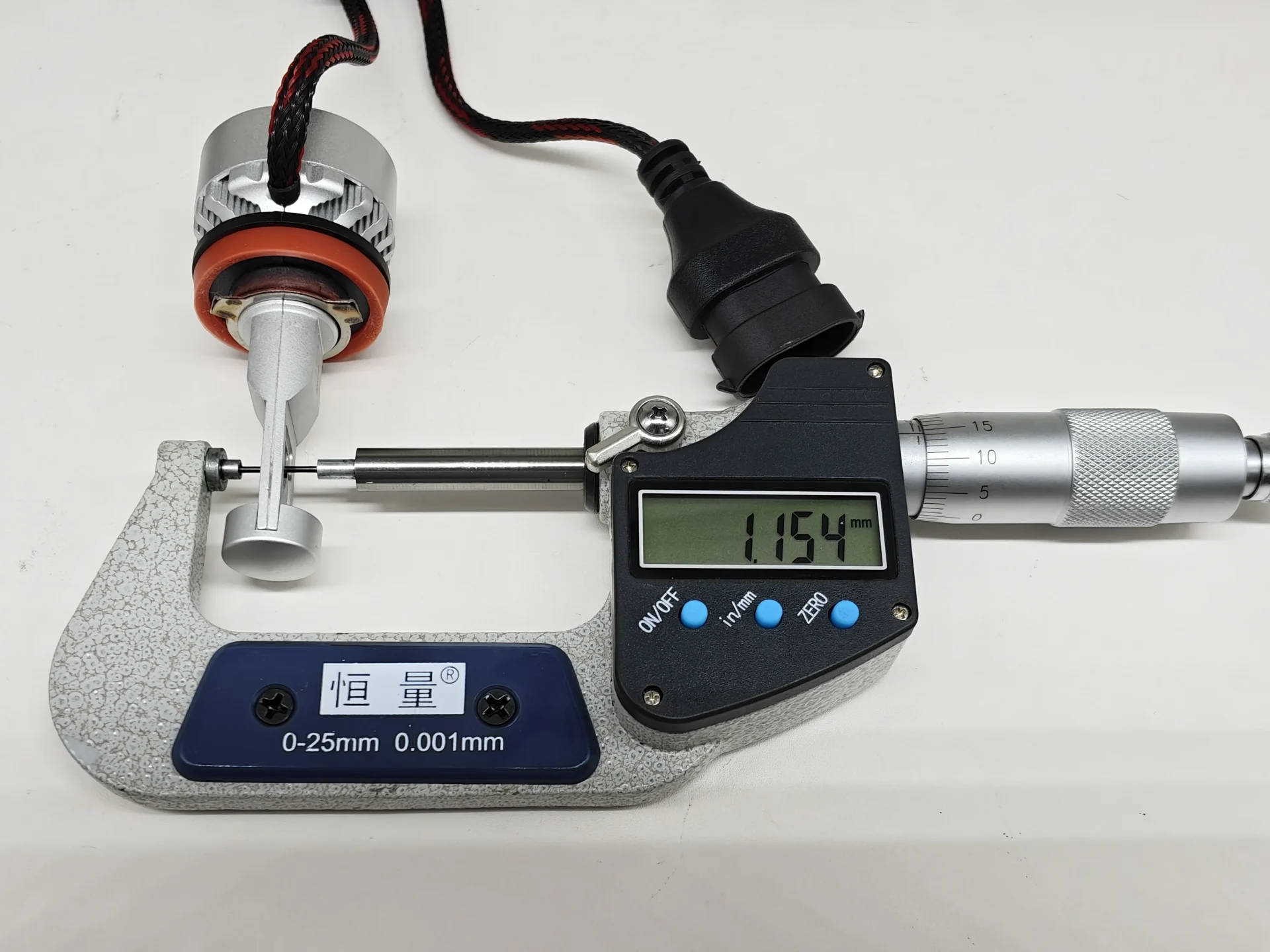
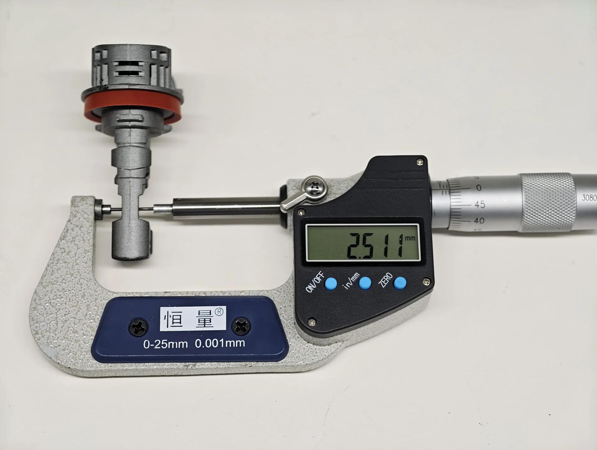
The micrometer spans the two outward-facing LED emitting surfaces. The H11 LEDr Configuration-2 reference calls this distance z and sets a maximum of 2.9 mm.
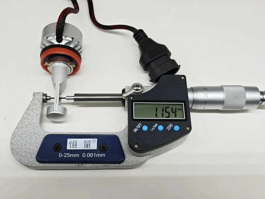
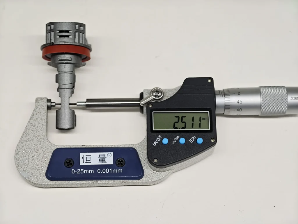
EB measures 1.154 mm and E4E 2.511 mm. EB’s opposing-surface distance is 1.357 mm smaller, or 54.04% lower than E4E’s. Both values are below the 2.9 mm dimensional reference. EB has the thinner measured dual-sided geometry; beam performance is compared in the projection tests below.
3.Box system reference-frame check
Areas A, B and C define the main emitting region. B1, B2 and B3 divide the core B region into three parts, while D checks unwanted emission outside the main area. The limits concern luminous flux in the specified viewing directions, not the percentage of bright pixels in a photograph.
| Area | UNECE requirement | What the area represents | Why it matters |
|---|---|---|---|
| A+B+C | ≥90% of total luminous flux E | Main effective emitting region | Shows whether most emitted light remains inside the defined region. |
| Area A | ≤10% of A+B+C | One side of the core emitting region | Limits excessive flux on one side of Area B. |
| Area B | ≥72% of A+B+C | Core emitting region | Requires most effective flux to remain in the central region. |
| B1, B2, B3 | Each ≥15% of Area B | Three subdivisions of Area B | Checks that the core output is distributed across all three sections. |
| Area C | ≤22% of A+B+C | Opposite side of the core emitting region | Limits excessive flux beyond the other side of Area B. |
| Area D | Required contrast between A+B+C and D | Region outside the main emitting area | Controls unwanted emission outside the intended region. |
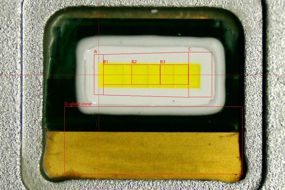
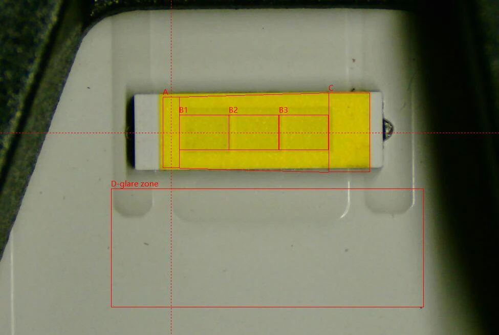
In both unlit records, the yellow emitting window spans B1, B2 and B3. E4E’s phosphor strip extends above and below the inner B rectangles while remaining close to the outer A–C boundaries.
4.Box system with the emitting area illuminated
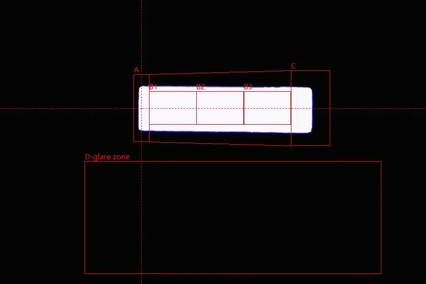
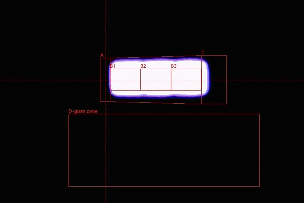
Both illuminated bands cover the full marked height of B1–B3, and both D regions remain visually dark. E4E’s band has gently uneven upper and lower edges and a violet-coloured fringe close to the bright perimeter. That fringe is around the main band, not a separate light patch inside D.
| Box-System Image Comparison |
|---|
| Area | Reference focus | EB observation | E4E observation |
|---|---|---|---|
| A+B+C | Main emitting envelope | Bright band remains within the upper framework. | Bright band also remains within the upper framework. |
| Area A | Emission on one side of B | A small part of the band reaches into A. | Bright emission begins close to the B1 boundary. |
| Area B | Core emitting region | Band covers the marked height of B. | Band also covers the marked height of B. |
| B1 / B2 / B3 | Distribution across all three subdivisions | One continuous illuminated band spans all three. | All three are covered by a continuous band with gently uneven edges. |
| Area C | Emission beyond the other side of B | Right end of the band extends into C. | Right end also extends into C. |
| Area D | Emission outside the main region | Visually dark; no obvious isolated bright marks. | Visually dark; no obvious isolated bright marks. |
| Item | EB | E4E | Result |
|---|---|---|---|
| Distance between opposing emitting surfaces | 1.154 mm | 2.511 mm | EB is 1.357 mm smaller (54.04%). |
EB’s clear measured distinction is the smaller opposing-surface distance. The Box images show a shared strength: both samples cover B1–B3 and keep D visually dark. E4E’s uneven bright perimeter is visible, but these photographs do not establish an EB advantage in B-region flux or D-region contrast. The numerical flux ratios would be needed to make that comparison.
Beam Pattern and Illuminance Comparison
The white-wall photographs show beam shape, the rainbow maps show the visible hotspot distribution, and the nine-point readings quantify where the two samples differ.
1.White-wall beam pattern
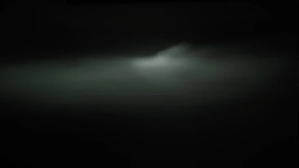
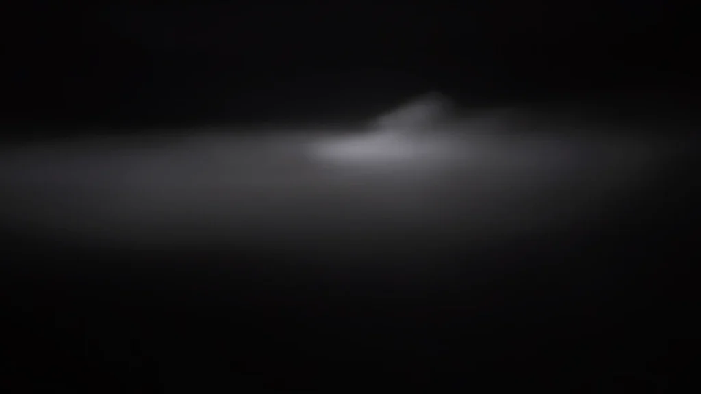
Both images show a horizontal cutoff leading into a rise on the right. EB has a compact bright patch below the transition. E4E also places its bright patch below the rise, with a broad surrounding field that fades towards the outer edges. The visible rise is pronounced in E4E, but its appearance alone does not determine the B50L result.
| Feature | EB | E4E | Related readings |
|---|---|---|---|
| Cutoff and rise | Horizontal cutoff with a right-hand rise | Horizontal cutoff with a pronounced right-hand rise | Assess B50L separately. |
| Main bright area | Compact patch below the central-right transition | Bright patch below the rise with a broad surrounding field | 50R, 75R and EMAX. |
| Outer distribution | Light fades towards the outer field | Light also fades towards the outer field | 25L, 50L, 25V and 50V distinguish local output. |
2.Rainbow map and hotspot distribution
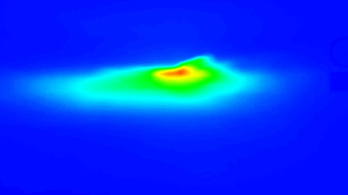
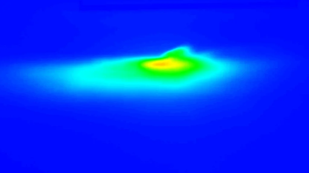
EB shows an orange-yellow core near the central-right transition. E4E shows an elongated yellow-orange core with a wider green and cyan surround. Both concentrate the visible hotspot near the rise, rather than distributing equal light across the whole field. Colour alone is not used to rank output; the measured peak and right-side points provide that comparison.
Both samples overlap the core B region and keep D dark in their Box images, yet their point readings differ. This shows why the source-position images and the complete beam measurements need to be read together: similar visible Box coverage does not mean identical illuminance distribution.
3.Nine-point illuminance with B50L focus
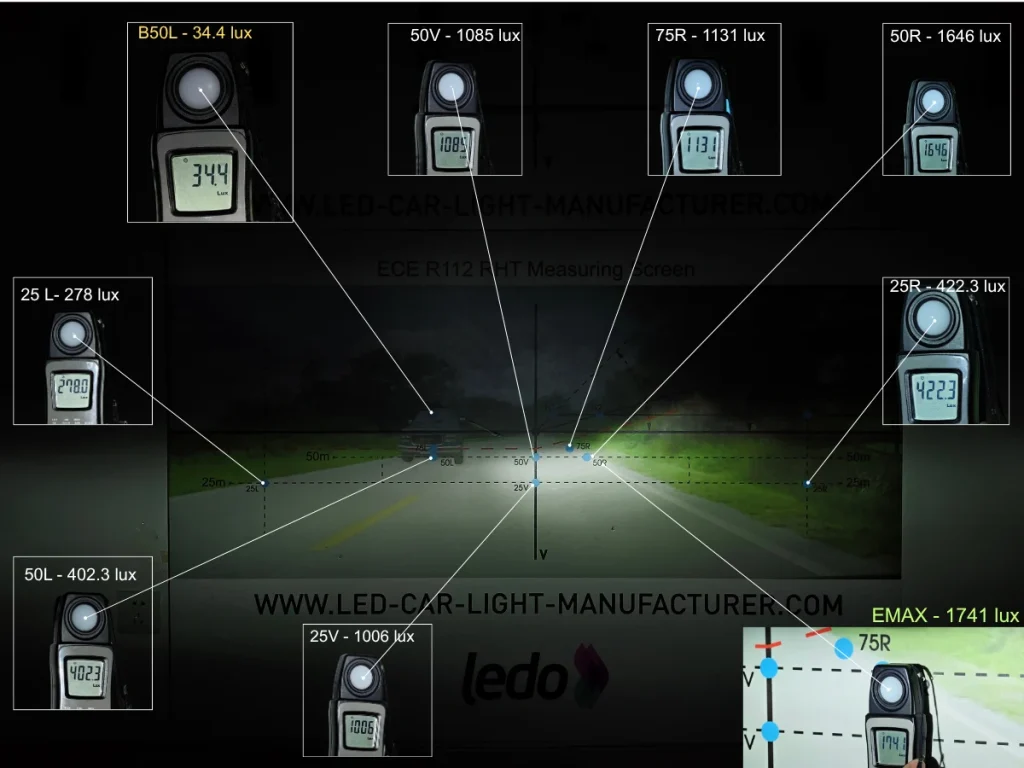
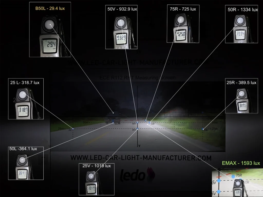
EB reaches 1,741 lux at EMAX, compared with E4E’s 1,593 lux. E4E records less light at B50L: 29.4 lux versus EB’s 34.4 lux. The peak-output advantage and the lower glare-point reading belong to different samples.
| How to Read the Nine-Point Results/Complete Nine-Point Illuminance Data |
|---|
| Point or group | Measurement purpose | Interpretation |
|---|---|---|
| B50L | Glare-control point above and left of the cutoff | Lower means less light at this point. |
| 50L | Controlled left-side distribution below the cutoff | Assess against the applicable upper and lower limits. |
| 25L | Left-side illumination | Higher means more light here; this is not the B50L glare point. |
| 50V / 25V | Central distribution | Shows how much light reaches the central reference points. |
| 75R / 50R / 25R | Right-side distribution | Compares the three right-side reference points. |
| EMAX | Peak illuminance | Records the highest measured illuminance. |
| Point | EB (lux) | E4E (lux) | EB − E4E (lux) | EB relative to E4E | Comparison |
|---|---|---|---|---|---|
| B50L | 34.4 | 29.4 | +5 | +17.01% | E4E records 5.0 lux less at this glare-control point. |
| 25L | 278 | 318.7 | −40.7 | −12.77% | E4E is higher at 25L. |
| 50L | 402.3 | 364.1 | +38.2 | +10.49% | EB is higher at 50L; applicable limits govern interpretation. |
| 50V | 1,085 | 932.9 | +152.1 | +16.30% | EB is higher at the central 50V point. |
| 25V | 1,006 | 1,019 | −13 | −1.28% | E4E is slightly higher at 25V. |
| 75R | 1,131 | 725 | +406 | +56.00% | EB is higher at 75R. |
| 50R | 1,646 | 1,334 | +312 | +23.39% | EB is higher at 50R. |
| 25R | 422.3 | 389.5 | +32.8 | +8.42% | EB is higher at 25R. |
| EMAX | 1,741 | 1,593 | +148 | +9.29% | EB records the higher peak illuminance. |
EB’s EMAX is 9.29% higher, and it is higher at all three right-side points, including 56.00% at 75R and 23.39% at 50R. E4E has the lower B50L reading by 5.0 lux: 29.4 versus 34.4 lux. It is also higher at 25L and slightly higher at 25V, while EB is higher at 50L and 50V. EB therefore offers higher measured peak and right-side output, while E4E places less light at the specific glare-control point. These 3.5 m values are sample comparisons, not a regulatory pass/fail test.
| Beam Pattern and Illuminance Comparison Summary |
|---|
| Comparison | EB observation | E4E observation | Result |
|---|---|---|---|
| White-wall beam pattern | Compact bright area below the central-right transition. | More pronounced rise with a broader surrounding field. | EB keeps the main bright area more concentrated. |
| Rainbow map | Compact orange-yellow core with a tighter surrounding gradient. | Elongated yellow-orange core with a wider green and cyan field. | EB concentrates energy more tightly around the hotspot, while E4E spreads it across a wider area. |
| Nine-point illuminance | Higher at 50L, 50V, 25R, 50R, 75R and EMAX. | Lower at B50L and higher at 25L and 25V. | EB records 9.29% higher EMAX and stronger output at all three right-side points; E4E records 5 lux less at B50L. |
EB combines a more compact hotspot with stronger centre-right and right-side illumination. It records 56.00% more light at 75R, 23.39% more at 50R and 9.29% higher EMAX. E4E’s main advantage is its lower B50L value, together with higher readings at 25L and 25V. For buyers prioritizing concentrated hotspot energy, peak illuminance and right-side road coverage, EB provides the stronger overall distribution.
Temperature and Fan Noise
This section compares emitting-area surface temperature after 30 minutes and operating noise measured 3.5 cm from the fan.
1.Emitting-Area Surface Temperature After 30 Minutes
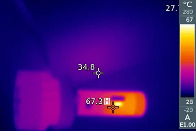
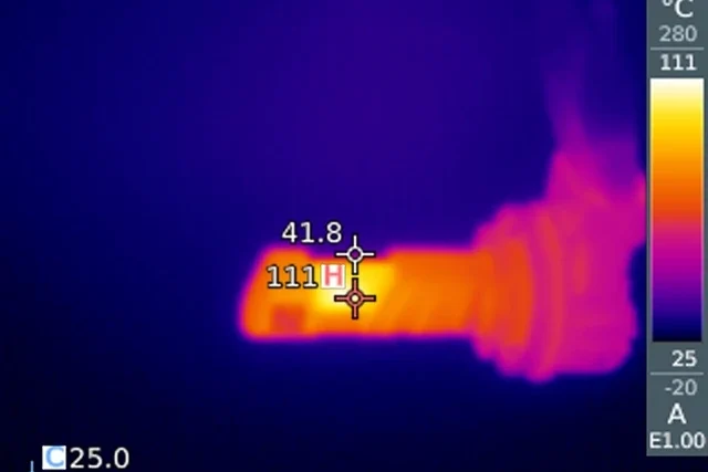
EB records 67.3°C at the emitting-area surface, compared with 111°C for E4E. EB is 43.7°C lower under the stated test conditions. These are surface readings, not LED junction temperatures or lifetime measurements.
2.Operating noise at 3.5 cm from the fan
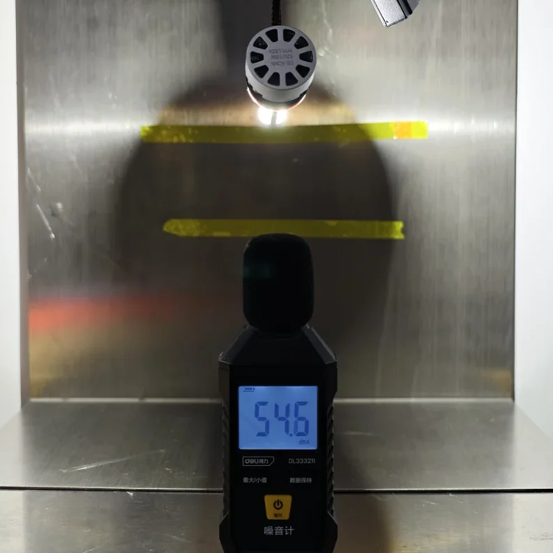
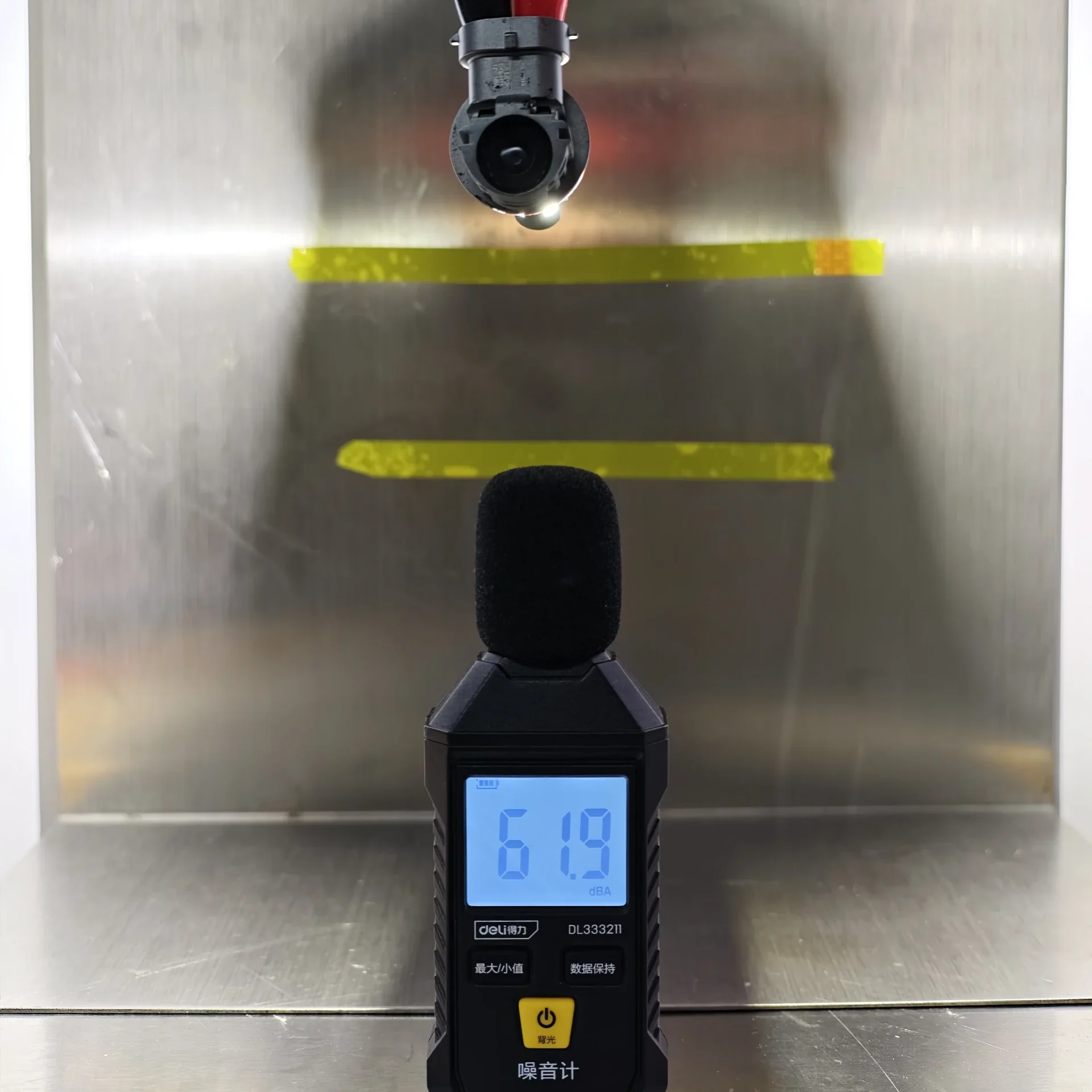
EB measures 54.6 dBA and E4E 61.9 dBA at the same close-range distance. EB is 7.3 dBA lower.
| Temperature and Fan-Noise Results |
|---|
| Metric | Condition | EB | E4E | Result |
|---|---|---|---|---|
| Emitting-area surface temperature | 13.2 V, 26°C, 30 minutes | 67.3°C | 111°C | EB is 43.7°C lower. |
| Fan noise | 3.5 cm from the fan | 54.6 dBA | 61.9 dBA | EB is 7.3 dBA lower. |
EB records both the lower emitting-area surface temperature after 30 minutes, by 43.7°C, and the lower close-range fan noise, by 7.3 dBA.
What This Comparison Means for Buyers
- Packaging: E4E uses 49.73% less box volume and 23 g less packaging weight. EB includes a hanging feature for peg-hook display, while E4E may require an additional hanger or alternative retail packaging.
- Construction: EB uses a dedicated H11 base with three locating tabs and a separate metal retaining spring. E4E has fewer external components, but the tested sample uses a universal base without a separate retaining spring.
- Emitting geometry: EB’s 1.154 mm opposing-surface distance is 54.04% thinner than E4E’s 2.511 mm structure. Both measurements remain below the 2.9 mm H11 LEDr Configuration-2 reference.
- Light distribution: EB records 9.29% higher EMAX and stronger readings at 25R, 50R and 75R. E4E has the lower B50L value and is higher at 25L and 25V.
- Temperature and noise: EB’s emitting surface is 43.7°C cooler after 30 minutes and its fan is 7.3 dBA quieter at 3.5 cm.
Overall conclusion: E4E offers the smaller and lighter package, but EB provides the stronger product-level combination of dedicated H11 mounting, spring retention, thinner emitting geometry, higher right-side and peak illumination, lower operating temperature and quieter cooling. For buyers prioritizing installation structure, optical performance and thermal control, EB is the more complete option.
EB vs E4E H11 LEDr FAQ
Author: Jack Liu, Co-founder & Product Director, LEDOAUTO
Regulatory check: LEDOAUTO Engineering Team, verified against official UNECE documents
Last updated: 27 Aug 2026
Update note: rewrote the comparison around reader-first explanations and section-specific insights while preserving the original measurements.
The category terminology used in this comparison follows the UNECE light-source category resolutions. Additional context is available in the ECE R37 H11 LEDr background.
References
E4E H11 LEDr Review: Construction, Beam Pattern, Illuminance, Temperature and Noise